
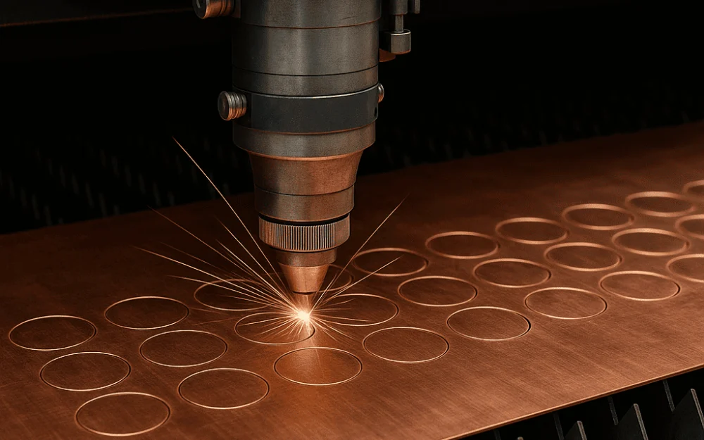
Copper is the nightmare material for fiber laser operators. At 1064 nm wavelength, copper reflects roughly 95% of the incoming beam. Its thermal conductivity is approximately eight times higher than carbon steel. Molten copper flows like water and does not stay where you put it. Every one of these properties requires a different response from the laser source — and they all occur simultaneously. This guide explains the physics behind each challenge, what it demands from the laser source specifically, and the process parameters that give copper cutting a reliable result.
Why copper is categorically different from every other metal you cut
Most metals present laser cutting with one primary challenge — reflectivity, or thermal conductivity, or low melting point, or high vapor pressure. Copper presents all of them at once, and they are not additive but multiplicative: each property makes the others harder to manage.
High reflectivity means the source must deliver much more incident power than will actually enter the material during the initial piercing phase. High thermal conductivity means that whatever energy does enter the material dissipates outward almost as fast as it arrives, requiring sustained high power density to maintain a melt front. Low melt viscosity means that once the material is molten, it behaves like a liquid metal bath rather than a viscous cutting front — high-pressure assist gas is needed to physically eject it before it re-solidifies in the kerf.
The result is a material that requires more power, faster cutting speed, higher gas pressure, more precise parameter control, and more robust source protection than any other common industrial cutting metal. Copper is not a material where you adapt your standard steel process — it requires a fundamentally different approach at every level, starting with the source specification.
The physics of copper’s reflectivity — why your laser source is at risk before the first cut
Why 95–97% reflectivity creates a back reflection event on every pierce
At room temperature, copper reflects approximately 95–97% of incident near-infrared laser energy. Research on coupling efficiency in laser processing of copper confirms that the surface reflectance of copper at 1 μm wavelength is approximately 97% in its untreated state — meaning only 3% of incident energy couples into the material. In practical terms, a 6 kW source directed at a cold copper surface delivers approximately 180 W of usable heating energy while reflecting approximately 5,820 W back into the delivery system — a back reflection event of enormous intensity happening on every single pierce, before any material processing has occurred.
This is not a risk that occurs occasionally or under unusual conditions. It occurs at the start of every cut, every time the laser pierces a new location on the copper sheet. The back reflection intensity during this cold-surface phase is as high as it will ever be, and it occurs at the moment when the source’s protection system has had no time to respond and establish any adaptive state. Modern fiber laser cutting machines address these issues through improved beam quality, anti-reflection technology, and stable power output — making high-speed and high-quality cutting possible, but only with the right source specifications.
How keyhole formation changes everything — and why you must get through the cold surface phase
The transition from cold surface to established keyhole is the defining event in every copper cut. Before keyhole formation: reflectance is at its maximum (~95%), effective absorption is at its minimum (~5%), and back reflection intensity is at its peak. After keyhole formation: the laser beam bounces multiple times off the vapor capillary walls inside the keyhole, with each bounce converting a fraction of the energy to heat. The degree of energy coupling changes dramatically during deep penetration processing, as the laser beam is reflected several times on the vapor capillary wall — the induced recoil pressure creates the keyhole depression, and multiple internal reflections allow the effective absorption to increase far beyond the flat-surface absorptance. Effective absorptance inside an established keyhole can reach 80% or higher.
The process implication is that every copper cut has two phases with fundamentally different physics. Phase 1 (pre-keyhole): low absorptance, high back reflection, maximum source risk, minimum cutting efficiency. Phase 2 (post-keyhole): high absorptance, reduced back reflection, stable cutting. The source must survive Phase 1 reliably enough to reach Phase 2 on every pierce — and the design of the piercing parameters is the primary tool for managing this transition safely.
Copper’s thermal conductivity — the second challenge that changes everything about process parameters
What 400 W/m·K actually means for laser cutting
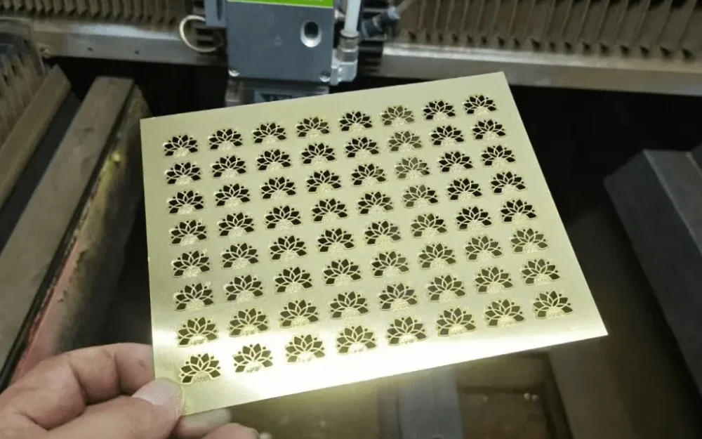
Copper’s thermal conductivity is approximately 400 W/m·K. Carbon steel’s is approximately 50 W/m·K. The ratio is roughly 8:1. In the context of laser cutting, this means that heat conducted laterally away from the cutting front into the surrounding material occurs eight times faster in copper than in carbon steel at equivalent temperatures.
The consequence is that the effective size of the melt zone that the laser can sustain — the region where material is at or above melting temperature at any moment — is dramatically smaller in copper than in carbon steel at the same incident power. More of the laser energy that enters the material is immediately conducted away from the cut zone rather than contributing to melting and vaporizing the kerf. High thermal conductivity dissipates heat quickly, reducing cutting efficiency and requiring higher power and more carefully optimized parameters compared to steel.
This thermal conductivity difference also means that the process window for copper cutting is narrower than for steel. In steel, the melt zone extends well beyond the immediate beam focus, providing some tolerance for parameter variation. In copper, the melt zone is tighter and more sensitive to changes in power, speed, and focus — meaning that parameter drift that would be invisible in steel cutting shows up immediately in copper cut quality.
Why “cut fast” is a physical requirement, not a style preference
High cutting speed in copper is not a throughput optimization — it is a thermal management requirement. At slow cutting speeds, the beam dwells at each point long enough for heat to conduct extensively into the surrounding material, increasing the size of the heat-affected zone while paradoxically reducing cutting efficiency by spreading the energy over a larger volume rather than concentrating it at the cut front.
For copper sheets 0.5–1 mm thick, cutting speeds of 10–20 m/min are achievable with sufficient power. At 1.5 mm, speed drops to 6–10 m/min. The key is to go fast — copper conducts heat so aggressively that slow speeds cause massive heat buildup, warping, and a poor edge finish. This is not a case where slower speed produces a cleaner cut. In copper, slower speed produces worse results because the thermal diffusion physics work against the cutting process at low speeds.
The practical setup implication is to establish the fastest stable cutting speed for each thickness first, then optimize power and gas pressure around that speed — rather than starting at moderate speed and trying to compensate with power. Speed is the primary lever for thermal management; power is secondary.
Source requirements — what a fiber laser source must have to cut copper reliably
Minimum power by thickness — the numbers that define feasibility
Copper cutting has real power floors below which the process is not reliably achievable regardless of parameter optimization. In many industrial applications, 1,000 W is considered a practical starting point for thin copper sheet. Below this threshold, the source cannot deliver enough power density to push through the cold-surface low-absorptance phase quickly enough to establish a keyhole before the heat diffuses and the incipient melt solidifies.
For 2 mm copper, 6 kW and above is recommended, with cutting speed at approximately 0.5–1.5 m/min. These power requirements are substantially higher than equivalent stainless steel thickness would demand, reflecting the combined effect of low initial absorptance and high thermal conductivity.
| Copper thickness | Minimum source power | Typical cutting speed | Nitrogen pressure | Notes |
|---|---|---|---|---|
| 0.5–1 mm | 1,000–1,500 W | 10–20 m/min | 10–14 bar | Minimum viable; 2 kW gives more margin |
| 1.5–2 mm | 2,000–3,000 W | 6–10 m/min | 10–14 bar | Pulsed pierce strongly recommended |
| 2–3 mm | 3,000–4,000 W | 4–7 m/min | 14–18 bar | Process window narrows significantly |
| 3–4 mm | 4,000–6,000 W | 2–4 m/min | 14–18 bar | Hardware back-reflection isolation required |
| 4–5 mm | 6,000–8,000 W | 1.5–2.5 m/min | 18–22 bar | High-power system; anti-spatter measures needed |
| Above 5 mm | 8,000 W+ | 0.5–1.5 m/min | 18–22 bar | Approaching practical limit; process stability variable |
Back reflection protection — hardware isolation is non-negotiable for copper
The back reflection event during copper piercing is not marginal — it is an extreme event that occurs on every pierce cycle, with reflected power approaching 95% of incident power during the cold-surface phase. Software-based back reflection protection (threshold detection followed by source shutdown) has an inherent response time in the range of several to tens of milliseconds. Catastrophic Optical Mirror Damage (COMD) events in laser diodes occur on timescales of microseconds to milliseconds — within the detection and shutdown latency of any software system.
For copper cutting specifically, the distinction between hardware isolation and software-only protection is not a premium feature versus a standard feature — it is the difference between a source that can reliably cut copper and one that is at material risk on every pierce. Cutting copper and highly reflective metals requires specialized protection. Without dedicated hardware, back-reflected energy leads to catastrophic lens damage, burnt fibers, and expensive source failures. Hardware isolation dissipates the back-reflected energy in a thermally managed structure inside the source before it can reach the pump diodes or delivery fiber — no detection response chain required, no latency.
When evaluating a fiber laser source for copper cutting applications, confirm explicitly: does this source include hardware optical isolation, or only software threshold protection? The answer must be hardware isolation. A source without it should not be used for copper cutting.
Dynamic power modulation — why MOPA has a structural advantage for copper
The two-phase nature of copper cutting — cold-surface high-reflection pierce followed by stable keyhole cutting — maps directly to MOPA architecture’s capability to independently control pulse width, peak power, and repetition rate. A MOPA source can be programmed to execute the pierce phase at low average power with high peak power pulses (maximizing instantaneous intensity for keyhole initiation while minimizing average back reflection energy), then automatically transition to a different parameter set for the stable cutting phase.
In pulsed mode, the high-peak-power beam is more easily coupled into highly reflective materials — enabling cutting at low average powers. In CW mode, intensity is limited to the average power of the laser and cannot achieve the coupling threshold on reflective materials. For a CW source, the piercing phase and cutting phase run at the same average power — there is no mechanism to reduce back reflection risk during the pierce without also reducing the power available for steady-state cutting.
MOPA is not a requirement for copper cutting — high-power CW sources with hardware back reflection isolation do cut copper at industrial scales. But MOPA’s parameter flexibility provides a meaningful process control advantage, particularly for thin copper (below 2 mm) where the narrow process window makes the pierce-to-cut transition management most critical.
The counterintuitive rule: why maximum power is not your friend when cutting copper
Every instinct in laser cutting points toward more power as the solution to difficult materials. Copper is the exception. A 6,000 W system cutting 4 mm copper runs well at around 4,000–5,000 W effective power. Going to full power causes the molten copper to splash upward and coat the nozzle.
The mechanism is copper’s low melt viscosity. Molten copper behaves much more like water than like molten steel — it flows readily in any direction the pressure gradient and gravity allow. At maximum source power, the keyhole generates molten copper faster than the nitrogen assist gas jet can eject it downward. The excess melt follows the path of least resistance upward, coating the nozzle, degrading the optical path to the workpiece, and producing a self-reinforcing degradation of cut quality.
The correct power calibration for copper is the minimum power that reliably maintains keyhole stability throughout the cut, not the maximum power available. This is typically 70–85% of the source’s rated output at the target thickness. Excess power on thin copper means the molten pool spreads too wide and you lose dimensional accuracy. Setting power at the minimum stable level for each thickness is not a conservative operating practice — it is the process-correct approach.
This power moderation principle also reduces thermal input to the part, which matters significantly for electrical applications where excessive heat affects copper’s mechanical and electrical properties in the material adjacent to the cut.
Assist gas — why nitrogen is the only viable option and how to specify it correctly
Why oxygen doesn’t work on copper
Oxygen-assisted cutting works in steel because the oxidation reaction between iron and oxygen is strongly exothermic — the chemical energy released by the reaction contributes to the cutting energy, effectively multiplying the laser’s effective power. The iron oxide layer that results is acceptable for most structural steel applications.
Copper’s oxidation behavior is fundamentally different. Copper and brass have high reflectivity and high thermal conductivity — they are already the most challenging metals for laser cutting. Oxygen assist does not provide the clean edge or controlled cutting environment these materials need. Use nitrogen for copper and brass regardless of cost preference. Copper oxide formation during cutting is not an acceptable trade-off: it produces an edge that requires secondary cleaning for any electrical application, and the oxide layer is a contaminant, not a process byproduct that can be left in place.
For electrical applications — busbars, connectors, motor windings, current-carrying components — an oxidized cut edge is a functional defect. Nitrogen is commonly used as the preferred assist gas for laser cutting copper when clean, oxide-free edges are required — especially important for electrical parts such as busbars, connectors, and other conductive components. There is no practical substitute.
Nitrogen pressure requirements — why copper demands more than stainless steel
Molten copper’s low viscosity is the physical reason that copper cutting requires higher assist gas pressures than most other metals. The gas jet must physically eject the low-viscosity melt from the kerf before it flows back into the cut and re-solidifies. Higher pressure is needed because the melt has less resistance to flowing in any direction — including back into the kerf — and the gas must overcome both gravity and surface tension to consistently move it downward and out.
For copper under 2 mm, nitrogen pressure of 10–14 bar works. For 2–4 mm, pressure should be 14–18 bar. For 5 mm and above, push toward 18–22 bar. These pressures are substantially higher than equivalent stainless steel cutting with nitrogen would require, and they impose real demands on the gas supply infrastructure — high-pressure nitrogen delivery systems, regulators rated for the required flow rates, and supply volume adequate to sustain cutting without pressure drops mid-job.
Gas purity for copper cutting should be 99.99% or higher for nitrogen. Oxygen contamination in the nitrogen supply directly produces the edge oxidation that nitrogen was chosen to prevent. Water vapor contamination degrades cut quality and contributes to optic contamination. Nitrogen purity for copper cutting is a non-negotiable specification, not a place to reduce cost.
The piercing problem — the most dangerous moment in every copper cut
Piercing is the highest-risk event in every copper cutting cycle. The combination of cold surface (maximum reflectance), full incident power (maximum back reflection energy), no assist gas keyhole established (no ejection path for molten material), and stationary beam (maximum dwell time and heat accumulation) occurs simultaneously at every pierce start.
Three approaches reduce pierce risk, in order of effectiveness:
Pulsed pierce: Rather than applying full cutting power at pierce initiation, apply a sequence of short, high-peak-power pulses at low average power to begin coupling into the cold surface. Each pulse initiates a small amount of surface heating; the cooling interval between pulses allows the surface to partially cool before the next pulse, preventing the uncontrolled melt pool that full-power piercing would create. Once evidence of coupling is observed (by monitoring back reflection or by time-based estimation), the parameter set transitions to the cutting parameters. This approach is most effective with MOPA sources, which allow precise independent control of pulse width, peak power, and repetition rate during the pierce phase.
Power ramp: On CW sources without MOPA capability, implement a power ramp at pierce start — beginning at 20–30% of cutting power and increasing linearly over a defined time to reach full cutting power once the keyhole has had time to initiate. This is less precise than pulsed pierce but provides meaningful protection compared to full-power immediate pierce.
Reduced initial power with increased duration: Set pierce power at 50–60% of cutting power and extend the pierce dwell time to compensate — the keyhole initiates more slowly but with lower maximum back reflection intensity. This approach trades pierce cycle time for back reflection risk reduction. For source protection on copper, this trade-off is consistently favorable.
Regardless of which approach is used, the pierce parameters for copper should be developed independently from the cutting parameters and never transferred from steel processes. The physics are different enough that steel pierce parameters applied to copper will either fail to pierce reliably or damage the source.
Application-specific considerations: electrical components, EV busbars, and precision copper parts
The majority of industrial copper cutting in fiber laser applications falls into one of three categories, each with specific quality requirements that go beyond general cut quality metrics.
Electrical busbars and power distribution components: Busbars carry high current. Any discontinuity in the cut edge — oxide layer, micro-cracks, heat-affected zone that has altered the copper’s grain structure — increases electrical resistance at the contact surface and creates a heat-generating point under load. For electrical parts such as busbars, connectors, and other conductive components, clean oxide-free edges are not an aesthetic requirement — they are a functional specification. Nitrogen assist with 99.99%+ purity, adequate power to minimize HAZ, and appropriate cutting speed are the source-level requirements that determine whether the cut part meets electrical performance specifications.
EV battery tabs and current collectors: Battery tab cutting operates at thicknesses (typically 0.05–0.5 mm) far below the standard copper cutting range, with cutting speeds exceeding 1 m/s at these thin dimensions. The quality requirement is laser-sharp edges with zero burr and HAZ measured in microns rather than millimeters — any thermal damage to the electrode coating adjacent to the cut line affects battery electrochemical performance. Battery electrode foils can be cut with 70–100 W pulsed fiber lasers at linear cutting speeds greater than 1 m/s. At these thicknesses and speeds, MOPA sources are dominant precisely because CW sources cannot achieve the HAZ control that ultra-thin copper foil cutting requires.
Precision machined parts and connectors: Dimensional accuracy on laser-cut copper connectors is typically tighter than equivalent sheet metal parts because the downstream application — mating electrical contacts, crimping, or soldering — has precise geometric requirements. The source-level implication is that beam quality (M² and BPP) matters more for copper connector cutting than for general copper sheet cutting — better beam quality produces a smaller, more consistent focal spot that translates directly into tighter dimensional tolerance on the cut part geometry.
Source selection checklist for copper cutting applications
Before specifying or purchasing a fiber laser source for copper cutting applications, verify each of the following:
Back reflection protection:
- [ ] Hardware optical isolation confirmed — not software-only threshold protection
- [ ] Manufacturer’s explicit rating for copper and brass cutting (not just general reflective material tolerance)
- [ ] Rated back reflection tolerance stated as an absolute power level or percentage
Power and beam quality:
- [ ] Rated output power meets or exceeds the minimum for the thickest copper in your application (from the table above)
- [ ] M² and BPP specified at rated output power — not at reduced test conditions
- [ ] For precision connector or thin-foil applications: M² ≤ 1.5 at rated power
Dynamic modulation capability:
- [ ] For pulsed pierce capability: confirm rise time, fall time, and modulation bandwidth
- [ ] For MOPA: confirm pulse width range (2–500 ns target), repetition rate range (to at least 200 kHz), and parameter set storage for pierce-to-cut switching
- [ ] For CW: confirm power ramp capability and ramp rate specification
Infrastructure requirements:
- [ ] Nitrogen supply rated for required pressure (up to 22 bar for thicker copper)
- [ ] Nitrogen purity specification: 99.99% minimum
- [ ] Chiller capacity includes margin above calculated thermal load (+20% minimum)
- [ ] Gas supply volume adequate for sustained high-pressure cutting without pressure drops
Warranty and manufacturer support:
- [ ] Manufacturer explicitly confirms warranty coverage for copper cutting application
- [ ] Back reflection events during copper cutting are covered, not excluded as “improper use”