
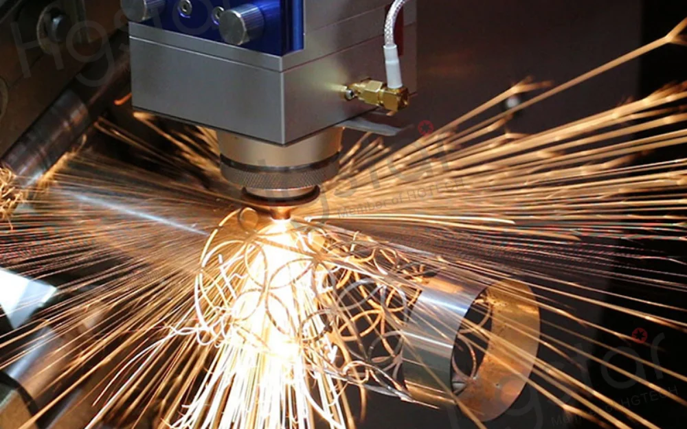
Aluminum is the second most commonly cut material on industrial fiber laser machines, after carbon steel. It is also the material most likely to produce unexpected quality problems — dross on the bottom edge, inconsistent piercing, parameter settings that work on one batch and fail on the next. Understanding why aluminum behaves the way it does under a fiber laser beam, and what the source specifically needs to handle it reliably, prevents most of these problems before they occur on the production floor.
How aluminum is different from copper — and why that matters for your source specification
If you have read about laser cutting of highly reflective metals, copper is usually the reference case — it is treated as the most challenging material, and aluminum is mentioned alongside it as similarly problematic. In practice, aluminum and copper are meaningfully different in their cutting behavior, and understanding the difference prevents both over-specifying (treating aluminum as if it were copper, adding unnecessary cost) and under-specifying (assuming that because aluminum is easier than copper, standard steel cutting source specs are adequate).
Aluminum’s room-temperature reflectance at 1064–1080 nm is approximately 92–95%. Copper’s is approximately 95–97%. That 3–5 percentage point difference sounds small, but it produces a material difference in cutting behavior: aluminum’s keyhole formation threshold is lower, the cold-surface phase is shorter, and the transition from low-absorptance to high-absorptance keyhole cutting happens more reliably at lower power levels. A 4 kW fiber laser cuts aluminum routinely. The same source attempting to cut copper of equivalent thickness faces a much harder process challenge.
The other key difference is temperature-dependent absorptance behavior. As aluminum heats up toward its melting point, its absorptance increases more dramatically than copper’s does per degree of temperature rise. This means that once a fiber laser source delivers enough power to begin meaningful surface heating on aluminum, the positive feedback loop toward keyhole formation is stronger than it is for copper. This does not eliminate the need for adequate power and back reflection protection — but it does make the process more manageable.
What aluminum shares with copper: it still requires substantially more source power than equivalent carbon steel thickness, still requires back reflection protection (particularly for thicker material and polished surfaces), and still requires nitrogen assist gas for most precision and high-quality applications. The source specification for aluminum is not the same as for carbon steel.
The physics of aluminum’s reflectivity — why it’s a challenge but not an impossibility
Aluminum’s room-temperature absorptance at 1064–1080 nm
At room temperature, aluminum absorbs approximately 5–8% of incident near-infrared laser energy. The remainder — 92–95% — reflects back from the surface. This places aluminum in the same category of high-reflectivity challenge materials as copper and brass, though its absorptance is measurably higher than copper’s and the practical cutting consequences are less severe.
The physical mechanism is the same as for all highly reflective metals: aluminum’s high free-electron density makes it an efficient optical reflector. The free electrons that make aluminum an excellent electrical conductor are also responsible for its reflective properties at near-infrared wavelengths. No source specification change eliminates this room-temperature reflectance — the response is to ensure the source has enough power to push through it to keyhole formation, and enough protection to survive the back-reflected energy during the piercing phase.
How aluminum’s absorptance increases with temperature — and why this helps at high power
Aluminum’s temperature-dependent absorptance behavior is more favorable than copper’s in the context of laser cutting. As aluminum heats up from room temperature toward and beyond its melting point, its absorptance increases from the initial approximately 5–8% toward 15–25% in the molten state — a larger fractional increase than copper experiences over the same temperature range. Once a keyhole is established, multiple reflections inside the vapor capillary drive effective absorptance to 80% or higher, which is similar to copper’s keyhole behavior.
The practical implication is that the transition from “cold surface reflecting most of the beam” to “established keyhole absorbing most of the beam” is faster and more reliable for aluminum than for copper at comparable power levels. A high-power fiber laser directed at aluminum surface will, with correct parameters, establish a keyhole relatively quickly. The window of maximum back reflection risk — the cold-surface phase before keyhole formation — is shorter than it is for copper. This is why aluminum cutting is achievable with standard CW fiber laser sources that are properly configured, whereas copper cutting at equivalent thickness genuinely benefits from MOPA architecture’s separate pierce-phase parameter control.
Power requirements for aluminum — and why aluminum needs more power than equivalent steel thickness
The 30–40% power premium over steel — where it comes from
Aluminum cutting requires typically 30–40% more power than equivalent steel thickness to achieve comparable cutting speed and quality. This premium reflects two additive factors: the higher initial reflectance (less of the incident power enters the material), and aluminum’s high thermal conductivity of approximately 200 W/m·K — approximately four times carbon steel’s — which causes heat to diffuse away from the cutting front faster than in steel.
The combined effect is that aluminum requires more power input to maintain the same energy concentration at the cut front. A source that cuts 6 mm carbon steel cleanly at 6 kW will typically need 6 kW+ to cut 4 mm aluminum with comparable quality — different thickness, comparable power requirement. This relationship is why aluminum cutting machine specifications typically call for higher source power than the maximum cutting thickness in carbon steel would suggest.
Minimum power by thickness — the feasibility table
The table below gives practical power reference points for aluminum cutting with nitrogen assist gas. These are industrial production reference values, not theoretical minimums — they reflect the power levels at which reliable, consistent cutting with acceptable edge quality is achievable in production conditions, not just in optimized laboratory settings.
| Aluminum thickness | Minimum source power | Recommended power | Cutting speed (N₂) | Cutting speed (Air) | N₂ pressure |
|---|---|---|---|---|---|
| 0.5–1 mm | 1,000 W | 1,500–2,000 W | 20–40 m/min | 25–50 m/min | 10–14 bar |
| 1–2 mm | 1,500 W | 2,000–3,000 W | 12–25 m/min | 15–30 m/min | 10–14 bar |
| 2–3 mm | 2,000 W | 3,000–4,000 W | 8–15 m/min | 10–18 m/min | 12–16 bar |
| 3–5 mm | 3,000 W | 4,000–6,000 W | 4–10 m/min | 5–12 m/min | 14–18 bar |
| 5–8 mm | 4,000 W | 6,000–8,000 W | 2–6 m/min | N/A — N₂ required | 16–20 bar |
| 8–12 mm | 6,000 W | 8,000–12,000 W | 1–3 m/min | N/A | 18–22 bar |
| 12–20 mm | 8,000 W | 12,000–20,000 W | 0.5–1.5 m/min | N/A | 20–25 bar |
| Above 20 mm | 12,000 W+ | 20,000–30,000 W | 0.3–0.8 m/min | N/A | 22–30 bar |
Note that the minimum powers represent the floor below which the process becomes unreliable in production conditions, not in optimized single-part settings. For thick aluminum above 20 mm, ultra-high-power lasers (20–30 kW+) with deeply negative focus positions (−8 to −15 mm) are required to effectively expel the large volumes of molten metal generated.
Back reflection protection for aluminum — necessary but different from copper
Why aluminum’s back reflection risk is real but more manageable than copper
The 3–5 percentage point difference in room-temperature reflectance between aluminum and copper translates into a meaningfully different back reflection risk profile. At 6 kW incident power on a cold copper surface, approximately 5,820 W reflects back toward the source. At 6 kW incident power on a cold aluminum surface, approximately 5,520–5,700 W reflects back — still an enormous amount, but the lower initial reflectance and faster temperature-dependent absorptance increase means the cold-surface phase is shorter, and the transition to stable keyhole cutting occurs faster.
This difference matters for source selection: while copper cutting effectively requires hardware optical isolation as a non-negotiable specification, aluminum cutting with an appropriately powered source that includes robust back reflection monitoring and protection — even software-based — can often be managed reliably. The key qualifier is “appropriately powered” — an underpowered source on aluminum will spend more time in the dangerous cold-surface phase on every pierce, increasing the cumulative back reflection exposure per cut.
When hardware isolation is required for aluminum vs. when software protection suffices
The decision follows the back reflection energy level and the source power, not the material alone:
Software protection typically adequate: Sources below 3 kW cutting aluminum up to 3 mm thickness on standard mill finish surfaces. At these power levels, the maximum back reflection energy during piercing is within a range that a well-designed software threshold system can monitor and respond to before cumulative damage occurs.
Hardware isolation strongly recommended: Sources above 6 kW cutting medium-to-thick aluminum; any power level cutting mirror-polished or highly reflective aluminum surfaces; production environments where the pierce cycle is repeated thousands of times per shift. At 6 kW+ on aluminum, the cold-surface back reflection event is in the same energy range as copper cutting at lower power — hardware isolation eliminates the response latency issue that makes software-only protection inadequate for copper.
Mirror-polished aluminum specifically: The reflectance of mirror-polished aluminum is approximately 95% — comparable to copper — and should be treated with the same source protection requirements as copper. Any source specification adequate for copper cutting is adequate for mirror-polished aluminum. A source specified only for standard aluminum without hardware isolation is at elevated risk on mirror-polished surfaces.
Surface condition — the variable that changes everything for aluminum
Mill finish vs. polished vs. anodized — three different cutting scenarios
Surface condition is the most commonly underestimated variable in aluminum cutting, and it is the primary reason why parameter sets developed on one batch of aluminum fail on another batch of nominally the same specification.
Anodized aluminum cuts and engraves very well — the anodized layer improves absorption and reduces reflectivity significantly compared to bare aluminum. Anodizing creates an aluminum oxide surface layer that absorbs near-infrared energy more effectively than the metal itself, making anodized aluminum the most favorable aluminum surface condition for laser cutting. Parameters developed on anodized aluminum will produce similar results consistently across batches, because the anodized layer is a controlled, consistent surface treatment.
Mill finish aluminum — the standard industrial surface condition — has absorptance in the 5–8% range at room temperature and represents the reference condition for most cutting parameter tables. Batch-to-batch variation in surface oxidation, roughness, and contamination produces moderate parameter sensitivity that most production environments manage by maintaining separate parameter sets for different material suppliers.
Polished or mirror-finish aluminum has absorptance at the low end of the room-temperature range — as low as 3–5% — and requires meaningfully higher power or lower cutting speed to achieve equivalent results. Polished or reflective surfaces can reflect the laser beam, reducing efficiency and potentially damaging the laser — a matte or anodized surface is more suitable for laser cutting. For production environments that regularly process polished aluminum, developing a dedicated parameter set and verifying back reflection protection adequacy is essential.
Why the same power setting won’t work across different surface finishes
The absorptance difference between anodized aluminum (significantly higher than bare metal) and mirror-polished aluminum (significantly lower than bare metal) can span a range of 3–5× in initial energy coupling efficiency. This is not a second-order effect — it is the difference between a process that works reliably and one that fails at the pierce or produces dross-covered edges. A parameter set optimized for mill finish aluminum will be too aggressive on anodized aluminum (producing burning at lower thicknesses, excessive dross at higher thicknesses) and too conservative on mirror-polished aluminum (failing to pierce reliably or producing rough edges).
The practical requirement is: maintain independent parameter sets for each surface condition you process regularly, and validate each set on representative material samples before production use. Do not transfer parameters between surface conditions without validation.
Aluminum alloys — why 5052, 6061, and 7075 cut differently
5052 series — the easiest aluminum to cut
5052 aluminum (an aluminum-magnesium alloy) is the most favorable common aluminum series for laser cutting. 5052 is very suitable for laser processing, offering excellent corrosion resistance and weldability, and cuts cleanly. The magnesium content slightly modifies the alloy’s melting and flow behavior, resulting in a less viscous melt that ejects more cleanly from the kerf with nitrogen assist gas. Bottom-edge dross is less severe on 5052 than on 6061 at equivalent parameters, and the parameter window for clean cutting is wider.
For general sheet metal fabrication, HVAC components, marine applications, and enclosures, 5052 is the baseline aluminum choice from a laser cutting process standpoint — more forgiving of parameter variation and more likely to produce consistent results across production batches.
6061-T6 — the most common alloy and its HAZ sensitivity
6061-T6 is the most widely used engineering aluminum alloy globally, and it is the alloy most commonly encountered in precision and structural laser cutting applications. While 5052 and 5083 offer excellent weldability and laser cut well, 6061 can be more difficult due to its higher strength and tendency to produce rougher edges.
The more significant issue with 6061 for structural applications is the T6 temper’s sensitivity to heat. T6 temper is achieved by solution heat treatment followed by artificial aging — a process that produces precipitation-hardened aluminum with significantly higher strength than annealed material. The T6 temper can soften near welds or heat-intensive processes — keeping heat input low helps preserve mechanical strength. In laser cutting, the heat-affected zone adjacent to the cut edge has been exposed to temperatures that dissolve the precipitation-hardened microstructure, producing a zone with lower strength than the parent material.
For non-structural applications — enclosures, brackets, panels — this HAZ softening is irrelevant. For load-bearing structural applications where the full T6 strength is required at the cut edge, the extent of the HAZ is a design consideration that should be addressed through parameter optimization (maximizing cutting speed to minimize heat input per unit length of cut) rather than through assuming the cut material retains its full T6 specification.
The practical source-level implication: higher cutting speed, even if it requires higher power to maintain, is preferable to lower speed with lower power on 6061-T6 structural applications. The additional power cost is justified by the reduction in HAZ width.
7075 — high-strength alloy with unique cutting challenges
7075 aluminum requires higher laser power levels and slower cutting speeds due to its high strength and hardness, and tends to produce rougher edges compared to 5052 or 6061. The high zinc content of 7075 (5.6–6.1%) modifies the alloy’s response to laser energy — zinc has a lower boiling point than aluminum, and preferential zinc vaporization during cutting can produce a different vapor composition in the kerf that affects assist gas dynamics and edge quality.
HAZ effects are also more severe in 7075 than in other common alloys. The high-strength temper of 7075 depends on a specific precipitation microstructure that is disrupted by the thermal exposure of laser cutting. For applications where 7075 is specified specifically for its high-strength-to-weight ratio — aerospace structural components, high-performance mechanical parts — the HAZ strength reduction may be a design concern that requires post-cutting heat treatment or mechanical sizing allowances.
From a source specification standpoint, 7075 cutting requires the upper end of the power range for the thickness being cut, and produces a narrower parameter window than 5052. Plan for more process development time when establishing 7075 cutting parameters.
Assist gas for aluminum — when nitrogen, when air, and when the choice matters

Aluminum is one of the few materials where air assist is sometimes a viable alternative to nitrogen — a situation that does not exist for copper or stainless steel. Understanding when this substitution is acceptable and when it is not prevents the common mistake of treating all aluminum applications the same.
When air cutting is acceptable: Thin aluminum (below approximately 4–5 mm), non-precision applications where some edge oxidation is tolerable, parts that will be powder-coated or painted (hiding the cut edge), and high-volume low-cost applications where the gas cost difference between air and nitrogen is commercially significant. Air cutting provides faster speeds and cost advantages for aluminum while supporting effective melt removal.
When nitrogen is required: Any application requiring weld-ready or anodize-ready edges (air-cut aluminum oxidizes at the cut surface, interfering with weld quality and anodizing adhesion); thicknesses above 5 mm (air does not provide adequate melt ejection force at these thicknesses); mirror or polished aluminum (oxide formation on the cut edge is more visible and more problematic); and all aerospace, automotive structural, and electrical applications with surface quality specifications.
Nitrogen is crucial for preventing oxidation and creating a clean, smooth edge for aluminum — particularly important for precision applications. The nitrogen pressure range for aluminum — 12–18 bar for thin-to-medium sheet, up to 25+ bar for thick aluminum — is lower than for copper at equivalent thickness, reflecting aluminum’s higher melt viscosity relative to copper. Gas purity should be 99.99%+ for any application requiring clean, oxide-free edges.
For any aluminum cutting application that will be followed by anodizing, nitrogen is non-negotiable. Air-cut edges do not anodize uniformly — the oxide layer formed during air cutting is different in structure from the anodizing oxide, producing visible color differences and adhesion problems at the cut edge.
Focus position — why aluminum cutting needs a different approach than steel
Why negative focus position improves aluminum cutting
Standard carbon steel cutting with nitrogen typically uses a focus position at or slightly below the material surface. Aluminum cutting benefits from a more significantly negative focus position — for medium-to-thick aluminum, a focus position of −2 to −4 mm below the surface is typical, and for thick aluminum above 20 mm, a deeply negative focus of −8 to −15 mm is required.
The physical reason is related to aluminum’s combination of high reflectance and high thermal conductivity. A more deeply focused beam — one whose focal point is inside the material rather than at the surface — distributes the laser’s energy over a deeper cross-section of the cut, maintaining adequate energy density throughout the kerf depth rather than concentrating it at the surface entry point. For materials that conduct heat rapidly away from the cut front (aluminum’s 200 W/m·K), maintaining energy density at depth is more critical than for steel, which retains heat in the cut zone more effectively.
A secondary effect is that the negative focus position reduces the peak intensity at the aluminum surface, which can reduce the severity of the initial back reflection event during piercing — a practical benefit that is particularly useful when hardware isolation is not available or when mirror-polished aluminum must be processed with software-only protection.
Focus position and dross formation — the connection most guides miss
Aluminum cutting produces large amounts of molten material that cools very rapidly due to aluminum’s high thermal conductivity. Focus position is one of the primary variables that determines whether this molten material is ejected cleanly from the kerf or re-solidifies as dross on the bottom edge.
If the focal point is too shallow (not negative enough), the bottom of the kerf does not receive enough energy to keep the molten material fluid long enough for the gas jet to eject it. The melt solidifies at the bottom of the kerf before it can be expelled, producing dross. If the focal point is too deep (excessively negative), the beam cross-section at the material entry point becomes too wide, producing excessive kerf width and thermal input that spreads heat into the surrounding material rather than concentrating it in the cut zone.
The optimization process for a new aluminum cutting application should include systematic variation of focus position as one of the first parameters — before adjusting power or speed — because focus position affects the efficiency of the entire energy delivery system, and getting it right makes subsequent power and speed optimization more productive.
The dross problem — what causes it and how to eliminate it
Bottom-edge dross — molten aluminum that re-solidifies and adheres to the lower cut edge — is the most common quality defect in aluminum cutting and the most frequent reason operators spend time on secondary deburring operations. Understanding the three-variable system that produces dross allows systematic elimination rather than trial-and-error parameter adjustment.
The physical mechanism: aluminum has a higher melt viscosity than copper, which means molten aluminum does not flow as freely. Combined with aluminum’s high thermal conductivity (which rapidly cools the melt at the kerf walls), molten aluminum has a narrower time window during which it is fluid enough to be ejected by the assist gas before it solidifies. Dross forms when the assist gas jet does not provide sufficient downward force to eject the melt in that window.
Three variables control dross formation:
Assist gas pressure: The most direct lever. High-pressure nitrogen (15–20+ bar) is required to forcefully eject the rapidly cooling melt before it solidifies into hard dross on the bottom edge. If dross is present at correctly set power and speed, increase gas pressure first before adjusting optical parameters.
Focus position: As described above, an insufficiently negative focus position leaves the kerf bottom under-energized, allowing the melt to cool and adhere before ejection. If dross persists after optimizing gas pressure, adjust focus position deeper (more negative) to improve energy delivery to the kerf’s lower portion.
Cutting speed: Very slow cutting speed allows excessive heat accumulation at the kerf bottom, producing a wide, over-melted zone that the gas cannot effectively clear. Increasing cutting speed (with a corresponding power increase to maintain cut quality) reduces the thermal footprint at any given kerf position and narrows the melt zone to a volume the gas jet can manage. Aluminum requires higher power and faster cutting speeds than equivalent steel to manage its thermal characteristics effectively.
If all three variables are optimized and dross persists, the source power is likely insufficient for the thickness being cut — the melt volume generated is too large for the gas pressure and speed combination to clear reliably.
Source selection checklist for aluminum cutting
Use this checklist when evaluating a fiber laser source for aluminum cutting applications:
Power specification:
- [ ] Source power covers the required thickness range with the 30–40% premium over equivalent steel accounted for
- [ ] For applications above 8 mm: confirm 8 kW+ minimum; above 12 mm: confirm 12 kW+ minimum
- [ ] For mirror-polished aluminum: add an additional power margin above the table values
Back reflection protection:
- [ ] For sources above 6 kW cutting aluminum above 5 mm: hardware isolation confirmed
- [ ] For mirror-polished aluminum at any power level: hardware isolation confirmed (treat as copper specification)
- [ ] For sources below 3 kW cutting thin aluminum with standard finish: software threshold protection acceptable with regular monitoring
Beam quality:
- [ ] M² and BPP specified at rated output power (not at reduced test power)
- [ ] For precision applications with tight dimensional tolerance: M² ≤ 1.5 at rated power
- [ ] For thick aluminum (above 10 mm): confirm beam quality is maintained at the high power levels required
Process capability:
- [ ] Negative focus position capability: confirm the cutting head supports the required negative focus range for target thickness
- [ ] Pierce parameter control: confirm ability to set separate pierce and cutting parameters
- [ ] Gas pressure infrastructure: confirm nitrogen supply rated to 25+ bar for applications above 8 mm
FAQ
Can I cut aluminum with the same laser source I use for carbon steel, just with different parameters? Yes, if the source has adequate power for the aluminum thickness you need to cut — which means 30–40% more than you would need for equivalent carbon steel. The other requirement is back reflection protection. A source specified purely for carbon steel cutting may not include back reflection protection adequate for aluminum, particularly at higher power levels. Before using a carbon steel source on aluminum, verify: (1) power is sufficient for the target aluminum thickness, (2) back reflection protection type and rating, and (3) whether the cutting head supports the negative focus position required for aluminum. If all three check out, the source can cut aluminum — the parameters will be different from steel, but the source capability is compatible.
Why does my aluminum cutting produce dross on the bottom edge even at correct power settings? The three most likely causes in order of frequency: insufficient nitrogen pressure (increase pressure first, especially for thicker aluminum); focus position too shallow (shift focus position more negative in 0.5 mm increments and test); cutting speed too slow for the power level (try faster speed with proportionally higher power). If all three are already optimized, the source power is probably below what the thickness requires — check it against the table in this guide. Thick aluminum produces large amounts of molten material that cools rapidly — high-pressure nitrogen is required to forcefully eject this melt before it solidifies into hard dross. If you are within the correct power range and pressure range, focus position optimization is usually the remaining variable.
Do I need nitrogen for aluminum, or can I use air? For thin aluminum (below 4–5 mm) in non-precision applications where edge oxidation is acceptable, air assist is a viable choice with the trade-off of some edge discoloration. For any application requiring weld-ready, anodize-ready, or visually clean edges — and for any thickness above 5 mm — nitrogen is required. Nitrogen prevents oxidation and achieves clean, smooth edges essential for precision applications. If the parts will be anodized after cutting, nitrogen is non-negotiable: air-cut edges anodize differently from nitrogen-cut edges due to the oxide layer formed during air cutting, producing visible color and texture differences at the cut edge.
Is mirror-polished aluminum as difficult to cut as copper? From a back reflection standpoint, yes — mirror-polished aluminum has a reflectance of approximately 95%, which is comparable to copper, and should be treated with the same source protection requirements. From a process standpoint, it is slightly easier than copper because aluminum’s temperature-dependent absorptance increase is stronger than copper’s per degree of heating, meaning the transition from high-reflection cold surface to stable keyhole cutting happens faster. But the source protection specification for mirror-polished aluminum should be the same as for copper: hardware optical isolation, not software-only protection. The process parameters — particularly piercing approach — should also follow the same gradual power ramp or pulsed pierce logic used for copper, not the standard mill-finish aluminum approach.