
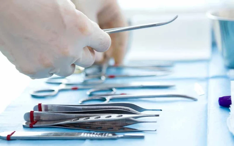
Medical device manufacturing uses fiber lasers for more applications than almost any other industry. It also imposes more demanding and more varied source requirements than almost any other industry. The same facility may need to cut nitinol stents with sub-5-µm kerf consistency, weld pacemaker housings to hermetic leak-free standards, mark every device with a permanent UDI code that survives decades of sterilization, and texture surgical instrument surfaces at the nanometer scale. Each of these processes places different requirements on the fiber laser source — and understanding those differences is the starting point for source selection in medical device manufacturing.
Why medical device manufacturing sets the highest bar for fiber laser source specification
Three layers of requirement compound on each other in medical device laser processing, creating a specification environment unlike any other industrial application.
The first layer is material sensitivity. Nitinol, 316LVM, Ti-6Al-4V, and cobalt-chromium alloys are not simply “difficult metals” in the industrial cutting sense — they are materials whose functional properties are defined by their microstructure, and laser processing parameters directly affect that microstructure. A heat-affected zone that would be irrelevant in a structural steel bracket can cause phase transformation in nitinol that produces micro-cracks leading to in-vivo stent fracture. The tolerance for thermal damage in medical device materials is orders of magnitude lower than in industrial fabrication.
The second layer is regulatory compliance. Medical laser welding tools must meet ISO 13485 quality management standards, FDA Regulations under 21 CFR Part 820 for Good Manufacturing Practices, ISO 10993 for biocompatibility testing, and ASTM F2063 and F136 for nitinol and titanium materials. These standards are not certification checkboxes — they define documentation, traceability, and process validation requirements that the laser source’s control system must support. A source without electronic parameter logging, validated process control, and calibration record support cannot meet these requirements regardless of its optical specifications.
The third layer is application diversity. A single medical device manufacturer may run four categorically different laser processes on the same production floor, each requiring a different source architecture. Selecting sources without this diversity in mind leads to either over-specification (paying for capabilities that specific applications do not need) or under-specification (discovering that a source adequate for cutting is inadequate for micro-welding).
The four laser processes in medical device manufacturing — and why each needs a different source
| Process | Typical application | Recommended source architecture | Power range | Pulse width | M² | Critical specification |
|---|---|---|---|---|---|---|
| Precision cutting | Stents, hypotubes, guide wires | Single-mode CW or MOPA fiber | 50–500 W | CW or < 10 ns | ≤ 1.1 | Minimum kerf width; HAZ control; dimensional repeatability |
| Micro-welding | Pacemaker housings, catheter joints, battery caps | QCW or pulsed fiber | 20–200 W | 1–50 ms (QCW) or < 10 ns | ≤ 1.3 | Pulse energy stability; penetration depth control; hermetic integrity |
| UDI marking | All implantable and reusable devices | MOPA fiber | 20–50 W | 2–200 ns (independent control) | ≤ 1.5 | Contrast without surface damage; sterilization resistance; biocompatibility |
| Surface texturing | Surgical instruments, orthopedic implants | Ultrashort pulse (ps/ns fiber) | 10–100 W | 1–100 ps or < 5 ns | ≤ 1.3 | Nanoscale uniformity; surface chemistry preservation |
The four processes span different power ranges, different pulse architectures, and different beam quality requirements. No single source architecture is optimal for all four — which is why larger medical device manufacturers typically maintain separate laser systems for cutting, welding, and marking/texturing, even when all systems nominally use “fiber laser” technology.
Cutting — stents, hypotubes, and precision tubing
Why stent cutting is the most demanding fiber laser cutting application
Cardiovascular stent manufacturing is widely cited as the most demanding application of fiber laser cutting technology in commercial production. The standard workhorse for producing bare metal stents is fiber lasers with fixed cutting heads, using a lathe-style configuration with a high-accuracy linear and rotary stage that moves a tubular workpiece beneath the laser beam.
Fiber lasers provide high throughput, precision, wall-plug efficiency, and repeatable results that make them the economical choice for stent cutting. The kerf width greater than 0.001″ (25 µm) that fiber lasers produce is actually an advantage for spiral-patterned stents that require this minimum kerf for the stent to flex correctly, and fiber lasers can cut thicker walls with little taper. The strut widths of modern coronary stents are typically 50–150 µm — meaning the laser kerf must be accurate to within a few microns of specification across hundreds of features on a single device, with zero inter-device variation in a production batch.
The beam quality requirement for stent cutting follows directly from this dimensional precision requirement. A source with M² of 1.05 focuses to a significantly smaller, more consistent spot than one with M² of 1.3 — at the focal lengths and spot sizes used in stent cutting, this difference in beam quality translates directly into a difference in kerf width consistency and minimum achievable feature size. For stent cutting, M² ≤ 1.1 is the practical specification floor.
Nitinol — the material that punishes heat-affected zones most severely
Nitinol (NiTi, nickel-titanium alloy) is the dominant material for self-expanding stents, guidewires, and orthopedic fixation devices. Its clinical utility comes entirely from its shape-memory and superelastic properties, which are defined by the alloy’s austenite finish temperature (Af) — the temperature above which the material fully transforms to its austenitic phase and exhibits superelasticity.
The Af temperature is sensitive to the alloy’s composition, heat treatment history, and microstructural state. When fiber laser cutting introduces a heat-affected zone adjacent to the cut kerf, the elevated temperature in that zone drives local phase transformation and recrystallization that alters the Af temperature relative to the bulk material. Stent manufacturing defects caused by improper laser cutting parameters can lead to serious clinical complications including allergic reactions, carcinogenesis, and stent failure — the HAZ must be minimized to preserve the nitinol’s critical shape-memory properties.
The consequences of HAZ-induced micro-cracks in nitinol are quantified in production data: a coronary stent project with a 2.5 mm diameter nitinol tube requiring ±0.005 mm tolerances found that prior-process HAZ inconsistency caused a 30% fatigue test failure rate, directly triggering a multi-month FDA authorization delay. Thirty percent fatigue failure is not a quality problem — it is a patient safety problem that delays regulatory clearance and creates product liability exposure.
The source-level response to nitinol’s HAZ sensitivity is the combination of maximum beam quality (smallest possible focused spot → narrowest kerf → minimum HAZ width) and optimized pulsing strategy (short pulses deposit energy faster than it can diffuse laterally → thermal confinement reduces HAZ). For nitinol stent cutting, the practical source specification is M² ≤ 1.1 with pulse widths in the nanosecond range and precise pulse energy control at ±0.5% or better.
316LVM and CoCr — different challenges, same beam quality requirement
Medical-grade 316LVM (low-vacuum-melt 316L stainless steel) is more forgiving than nitinol from a phase transformation standpoint — it does not have a shape-memory microstructure that HAZ can disrupt. Its primary laser cutting challenge is the recast layer: the thin zone of re-solidified material that forms at the cut edge, which has different surface chemistry from the bulk 316LVM.
The clinical concern with recast layer on 316LVM implants is nickel ion release. Recast material has higher surface area and different oxide composition than the underlying bulk, which increases the rate of nickel dissolution in physiological fluids — a biocompatibility concern particularly for long-term implants. Medical laser cutting must produce cuts that are burr-free and recast-layer-free, as surface residues directly affect biocompatibility. Minimizing recast layer requires minimizing HAZ, which returns to the same source specification: high beam quality and short pulses.
Cobalt-chromium alloys (CoCr, such as L605) are used for balloon-expandable stents where higher radial strength is required than nitinol provides. CoCr has a higher melting point than 316L and generates metallic debris during cutting that must be completely removed by the assist gas to prevent cobalt ion contamination of the implant surface. High-pressure inert gas assist (nitrogen or argon) is essential for CoCr stent cutting.
Micro-welding — pacemakers, catheters, and implant assemblies
What medical micro-welding requires from a laser source
Medical laser micro-welding requires reproducible pulses, small spot diameters, and precise penetration control — welds that hold together parts used or implanted during surgery, where weld integrity is critical for patient health. The resulting penetration and weld spot sizes are typically under 1 mm, making this process correctly called laser micro-welding. Applications include pacemaker housings, surgical blade assemblies, endoscopic instrument joints, catheter tip attachments, and battery cap seals.
The source requirement for micro-welding differs fundamentally from cutting. Cutting requires minimum kerf width — a small, tightly focused spot. Micro-welding requires controlled penetration depth and stable melt pool formation — which depends on pulse energy reproducibility, spot size consistency, and the ability to control the peak power-to-average power ratio. Multiple source architectures are suitable for micro-welding: pulsed Nd:YAG, CW fiber, nanosecond fiber, QCW (quasi-continuous wave) fiber, and high-brightness direct-diode lasers each have advantages for specific material combinations and penetration requirements.
Pacemaker hermetic sealing — the most stringent micro-welding application
Pacemaker and implantable cardiac defibrillator (ICD) housings must achieve hermetic sealing: a weld with zero porosity, zero micro-cracks, and no leakage detectable by helium leak testing. The housing is typically titanium, and the weld must seal the battery and electronic components from the body’s fluid environment for the full device life — which may be a decade or more.
Hermetic welding of titanium pacemaker enclosures requires controlling heat input to the micron level, guaranteeing absolute seal integrity without thermal warping. The standard acceptance test is a helium leak test, which detects any gas passage through the weld at the molecular level. A weld that passes visual inspection and even X-ray inspection may fail a helium leak test if it contains a micro-channel below visible resolution.
QCW fiber laser sources are particularly well-suited to hermetic welding of titanium. The QCW architecture delivers peak power 5–10× the average power rating in each pulse — sufficient to achieve keyhole-mode penetration — while the extended pulse duration (milliseconds) allows the melt pool time to flow and consolidate before solidification, eliminating the micro-porosity that short pulses can leave. Argon shielding gas is required for titanium, and the delivery system must be leak-tested to prevent any oxygen ingress into the weld atmosphere.
Nitinol micro-welding — attaching marker bands and joining struts
Nitinol stent assembly includes a welding process that combines nitinol with platinum-iridium (Pt-Ir) alloy — the radiopaque marker bands that allow the stent to be visualized under X-ray fluoroscopy during and after implantation. This is among the most challenging micro-welding applications in medical device manufacturing.
Nitinol and Pt-Ir have melting points that differ by approximately 400°C (NiTi ≈ 1,310°C; Pt-Ir ≈ 1,770°C). When the two materials are welded, the relative proportions of each in the melt pool — the dilution ratio — must be controlled tightly to prevent the formation of brittle intermetallic compounds at the weld interface. By strictly controlling the laser parameters, the dilution ratio of the two metals in the melt pool can be managed to prevent brittle intermetallic phase formation. This requires pulse energy control at ±0.5% repeatability or better — a specification that only MOPA architecture fiber laser sources can consistently provide across thousands of welds in a production run.
UDI marking — the regulatory driver that every medical device manufacturer faces
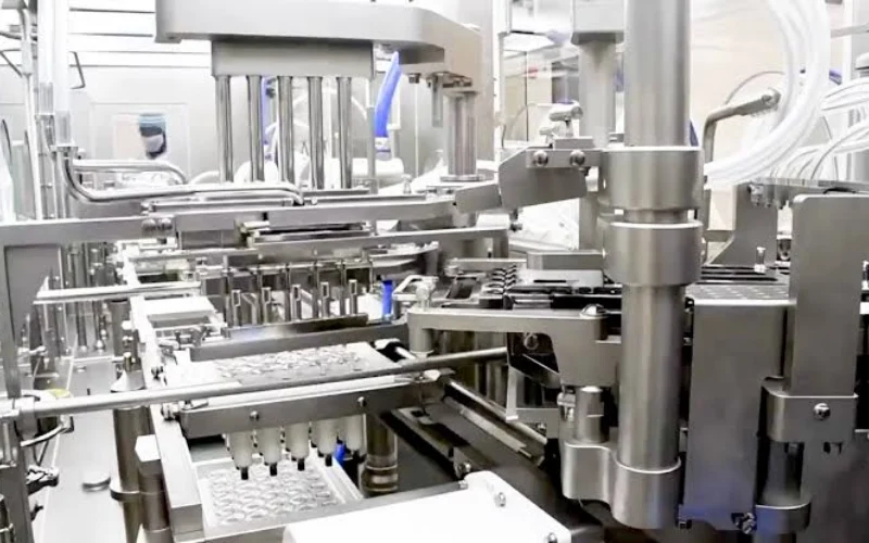
What FDA UDI requires and why only laser marking satisfies it
The FDA’s Unique Device Identification system requires that medical devices carry a permanent, machine-readable code linking each device to its manufacturer, model, production batch, serial number, and expiration date. For reusable devices that are separated from their packaging during use — surgical instruments, orthopedic implants, endoscopes — the mark must be on the device itself. The mark must survive manufacturing, sterilization, surgical use, and in some cases decades inside the human body.
Only laser marking consistently produces identifiers that survive this full lifecycle. Ink marking washes off in sterilization. Electrochemical etching creates recesses that harbor bacteria. Mechanical stamping creates stress concentrations that can initiate fatigue cracks in thin-walled implant components. Laser marking, properly executed, produces a permanent mark at the device surface that can be read by standard barcode scanners, survives autoclave sterilization cycles, and does not compromise the device’s structural integrity or biocompatibility.
MOPA vs. standard CW fiber laser for UDI marking — why pulse control matters for biocompatibility
The choice of laser source architecture for UDI marking on implantable devices is not merely a quality preference — it is a biocompatibility decision.
Standard CW fiber laser marking of stainless steel produces material removal (ablation) in the marked area. Ablation creates surface micro-features — small pits and grooves — that can trap bacteria and resist cleaning, creating potential infection vectors in surgical instruments and implants. This is particularly problematic for reusable instruments that must be sterilized between uses.
For titanium implants, MOPA short-pulse annealing produces color marks through thin-film optical interference in the titanium oxide layer — the same mechanism that produces heat tint colors on welded titanium. By controlling the pulse width precisely, the oxide layer thickness can be set to produce a specific color (typically black or dark gray for UDI readability), without ablating the underlying titanium or disrupting the stable TiO₂ passive layer that provides titanium’s biocompatibility.
The source specification for implantable device UDI marking: MOPA architecture with independently controllable pulse width from approximately 2 ns to 200 ns, at 20–50 W average power. The independent pulse width control is the feature that allows optimization of the oxide layer thickness for each material — it cannot be replicated with standard Q-switched sources whose pulse parameters are coupled.
Surface texturing — the emerging laser process for surgical instruments
Surface texturing using fiber laser sources has emerged as a functional manufacturing process for surgical instruments, addressing two problems simultaneously: operating room glare and infection control.
This is a categorically different laser-matter interaction from cutting or welding. Surface texturing does not remove bulk material or create a through-cut — it modifies the surface morphology at sub-micron scale through controlled ablation of surface material to create a periodic micro/nano structure. The requirements: ultrashort pulse width (picosecond or sub-10-nanosecond range) to create ablation without excessive thermal spread that would smear the texture geometry; very high beam quality (M² ≤ 1.3) to focus to the small spot size needed for sub-micron feature creation; and precise overlap control to ensure uniformity across the entire instrument surface.
The source requirements for surface texturing overlap with those for UDI marking in some respects (small spot, pulse control) but differ in the scale of surface modification targeted. A MOPA fiber laser source in the 10–50 W range with sub-10-ns pulse width capability can cover both UDI marking and light-surface texturing on a single platform, making it a versatile choice for facilities that need both capabilities.
Regulatory compliance — what ISO 13485 and FDA 21 CFR Part 11 mean for source selection
ISO 13485 — the quality system that governs medical device laser processing
ISO 13485 is the quality management system standard specifically for medical device manufacturing. Its requirements for laser processing equipment go beyond “the laser must work correctly” — they include documented process validation, calibration maintenance, and the ability to demonstrate process repeatability over time.
For fiber laser source selection, ISO 13485 compliance means the source must support Installation Qualification (IQ), Operational Qualification (OQ), and Performance Qualification (PQ) protocols — the three-stage validation process that confirms a piece of equipment is installed correctly, operates within specified parameters, and consistently produces results that meet specification. Ask source suppliers explicitly whether they can provide documentation support for IQ/OQ/PQ validation, including parameter specification sheets for the validated operating range, calibration protocols, and test reports from factory acceptance testing.
ISO 13485 requires that laser process parameters be locked and controlled — operators cannot modify validated parameters without a change control process. The source’s control interface must support parameter set locking: once a process recipe has been validated, the power, pulse width, repetition rate, and other parameters must be fixed against unauthorized modification. Sources without this capability require workaround controls that are harder to maintain and harder to demonstrate in an audit.
FDA 21 CFR Part 11 — electronic records and source traceability
According to FDA Title 21 CFR Part 11 requirements, manufacturers must maintain records of each step of the manufacturing process, including the cutting of stents and other medical devices. For laser processing, this means every production run must be accompanied by a record that documents the actual laser parameters used — not just the nominal programmed values, but the actual measured values during processing.
This requirement has a specific implication for source selection: the laser source and its control system must be capable of logging actual process parameters (output power, pulse energy, speed, focus position) per production batch, in a format that can be exported and retained as an electronic record. A source that displays parameters on a panel but does not log them electronically requires manual record-keeping workarounds that are harder to audit and more prone to errors.
For aerospace titanium cutting, the CNC controller records the exact power, speed, and gas pressure used for every job — this digital thread of traceability is what auditors require. The same standard applies in medical device manufacturing: the complete process record must be traceable from the raw material heat number through every processing step to the finished device.
Key materials in medical device laser processing — source requirements by material
| Material | Primary applications | Recommended source | Pulse width | M² | HAZ sensitivity | Key constraint |
|---|---|---|---|---|---|---|
| Nitinol (NiTi) | Stents, guidewires, orthopedic clips | Single-mode MOPA fiber, or ultrashort pulse | < 10 ns | ≤ 1.1 | Extreme — micro-cracks at Af temperature boundary | Phase transformation must not occur in HAZ |
| 316LVM (medical SS) | Surgical instruments, stent scaffolds, hypotubes | Single-mode CW or MOPA fiber | CW or < 20 ns | ≤ 1.2 | Moderate — recast layer biocompatibility concern | Recast layer must be minimized for nickel ion control |
| Ti-6Al-4V (Grade 5) | Orthopedic implants, spinal devices, dental | Single-mode MOPA, argon assist | < 10 ns | ≤ 1.2 | High — alpha case formation above 450°C | Argon shielding mandatory; see titanium cutting guide |
| Cobalt-Chromium (CoCr) | Balloon-expandable stents, heart valves | Single-mode CW or MOPA fiber | CW or < 20 ns | ≤ 1.2 | Moderate | High-pressure inert gas for debris clearance |
| Platinum-Iridium (Pt-Ir) | Marker bands, electrode tips | MOPA fiber | < 5 ns | ≤ 1.1 | Low — high melting point | Used in dissimilar metal welding with nitinol |
| PEEK / biopolymers | Spinal cages, suture anchors | CO₂ or UV laser preferred | N/A | N/A | N/A — different interaction mechanism | 1064 nm fiber laser not suitable for most polymer cutting |
Note on PEEK and biopolymers: standard 1064 nm fiber laser sources are poorly suited for cutting PEEK, UHMWPE, and most medical polymers because these materials have very low absorption at near-infrared wavelengths. CO₂ lasers (10.6 µm) or UV lasers (355 nm) are the appropriate choices for polymer medical device cutting — confirm material absorption at the intended wavelength before specifying a fiber laser source for polymer applications.