
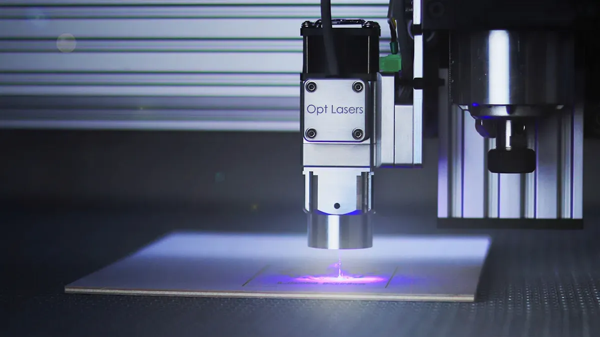
When a fiber laser machine starts cutting poorly — inconsistent depth, incomplete penetration, rough edges, unexplained slowdowns — the instinct is often to blame the laser source. In most cases, that instinct leads to the wrong place first. Apparent power loss at the workpiece has at least six distinct causes, only one of which is actual source degradation, and the others are faster to check, cheaper to fix, and statistically more likely to be the culprit. This guide walks through the diagnostic sequence in the order that minimizes downtime: cheapest and fastest checks first, source-level investigation last.
The most important first step: confirm the drop is actually from the source
Output power loss at the workpiece and output power loss at the laser source are not the same thing. They produce identical symptoms — cuts that don’t penetrate, speeds that need adjustment, edge quality that has deteriorated — but they have completely different causes and completely different fixes. Jumping straight to the source is the most common diagnostic mistake, and it wastes the time that should have been spent on the actual problem.
The disciplined approach is to trace the path of light backward, beginning with the component nearest the workpiece and working toward the source only after ruling out everything closer to the cut zone. This is not just a procedural preference — it reflects the statistical reality that contaminated optics, degraded consumables, gas supply issues, and cooling system derating are each individually more common causes of apparent power loss than actual source degradation in a machine that has not recently experienced a triggering event.
The six-step sequence that follows is ordered by a combination of check speed, fix cost, and frequency. Complete each step before proceeding to the next. If a step reveals the problem, stop there — do not continue checking further causes in the hope of finding something more interesting.
Step 1 — Check the cutting parameters before touching any hardware
Verify the power setting hasn’t been accidentally changed
Before touching a single piece of hardware, open the CNC control and verify that the cutting program’s power percentage, focus height, and assist gas pressure settings match the known-good values for the material and thickness you are cutting. This check takes thirty seconds and catches one of the most commonly overlooked causes of apparent power loss: parameter values that have been changed accidentally or intentionally by a previous operator, a software update, or a job import that overwrote the active settings.
A machine cutting at 80% of its intended power because a previous operator manually reduced the setting produces exactly the same symptoms as a machine whose source has degraded by 20%. The difference is that the former is resolved in five seconds by correcting the value; the latter requires investigation and possibly repair. Always check parameters first.
Check the focus position — thermal lensing from dirty optics shifts the focal point
If parameters are confirmed correct and the problem persists, check the programmed focus position against the last known-good setting for the current material. This step deserves explanation, because the mechanism is not obvious.
Contamination on optical components such as the protective window, focusing lens, or collimator creates a thermal lensing effect — the absorbed energy heats the optical element unevenly, changing its refractive index and effectively converting it into a weak lens that shifts the beam’s focal point. A focal point that has shifted 0.5–1 mm from its nominal position delivers dramatically lower power density at the material surface — the beam is no longer at its tightest, most intense point when it contacts the material. The source is outputting exactly the same power as before; less of it is arriving at the kerf in a usable form.
This means that a contaminated protective window causes two compounding problems: direct absorption of laser energy by the contaminant, and focal point displacement that reduces effective power density independently. Both are resolved by replacing the window — but understanding the thermal lensing mechanism explains why even a mildly contaminated window can produce larger performance effects than the visible contamination level would suggest.
Step 2 — Inspect the cutting head optics: the most common cause of apparent power loss
Start with the protective window — it fails most often
The protective window is the optical element positioned between the focusing lens and the workpiece. It exists specifically to absorb contamination before it reaches the more expensive focusing lens. As a result, it is the most consumed optical element in fiber laser systems — and the most common single cause of apparent power loss.
Fiber lasers have a very small beam size with very high power density, which means any contamination on the protective window or lens creates an instant loss of cut quality. Unlike CO₂ lasers, where operators clean and reinstall optics as a daily routine, fiber laser protective windows are typically replaced rather than cleaned once contamination has progressed beyond a fresh deposit — the high power density means that contaminants bake onto the surface rapidly and cleaning attempts risk scratching the optical coating.
To inspect: remove the protective window cartridge according to the machine manufacturer’s procedure. Hold the window under a bright directional light and examine both surfaces for cloudiness, discoloration, brown or black spots, micro-cracks, or surface pitting. Any of these indicate replacement is needed. Audible popping or crackling sounds during cutting are a real-time indicator that the laser beam is striking contamination on the optical surface — if this has been occurring, inspect the window immediately rather than waiting for a scheduled check.
Check the focusing lens and collimating lens
If replacing the protective window does not fully resolve the performance drop, the problem may have propagated to the focusing lens or collimating lens — either through direct contamination that bypassed the protective window, or through thermal damage from a contaminated window that was operated past its usable life.
Inspect the focusing lens using the same bright-light visual technique. Haze, coating damage, or any permanent discoloration indicates the lens needs replacement — these cannot be corrected by cleaning. A focusing lens that has experienced thermal damage from a burnt protective window will show a characteristic central discoloration at the beam path center, distinct from edge contamination. If internal optical elements of the cutting head are damaged, the optical path becomes abnormal and reflected light causes excessive heating at the fiber output head, potentially leading to burnout of the QBH or LOE crystal — making early detection of lens damage critical to preventing escalating repair costs.
Inspect the nozzle — a damaged or misaligned nozzle distorts gas flow and apparent cutting power
The nozzle does not affect the laser beam’s optical power, but it controls how assist gas is delivered to the cut zone, which directly affects how efficiently molten material is ejected and how cleanly the kerf forms. Burr formation on materials that previously cut cleanly points to issues with the nozzle’s integrity, gas flow, or a degraded focus lens. A nozzle with a damaged or non-circular orifice, a blocked tip, or misalignment relative to the beam axis produces cuts that appear underpowered because material ejection is inefficient — not because less optical power is being delivered.
Check the nozzle orifice visually for roundness and cleanliness. Replace if deformed. Verify nozzle alignment by running a low-power centering test according to your machine’s procedure. A misaligned nozzle is one of the fastest and cheapest fixes in this entire sequence — a replacement nozzle costs a few dollars and installs in minutes.
Step 3 — Check the assist gas supply and quality
The first and most critical variable in fiber laser cutting performance is the quality of the assist gas — it must be contamination free. This is TRUMPF’s technical support manager’s direct assessment, and it captures a reality that troubleshooting sequences routinely underweight: gas supply problems produce symptoms that are nearly indistinguishable from optical or source power loss.
A nitrogen supply running at insufficient pressure produces cuts with oxidized edges and reduced penetration — identical symptoms to a 10–15% source power reduction. An oxygen supply contaminated with moisture produces inconsistent exothermic reaction at the kerf, resulting in variable penetration depth. An air compressor with a degraded oil-water separator introduces oil aerosol into the gas path, which contaminates the cutting head optics from below — causing progressive window and lens degradation that then compounds the apparent power loss.
Check in this order: confirm the gas cylinder or supply pressure gauge shows adequate pressure for the current application (not just above zero — verify against the programmed cutting pressure plus system losses). Check the inline filter and dryer condition on any compressed air supply. If using nitrogen or oxygen from cylinders, verify the purity grade matches the application requirement. For stainless steel cutting with nitrogen, industrial-grade (99.5%+) is the appropriate minimum; lower purity introduces oxygen that causes edge oxidation that can be mistaken for insufficient power.
Step 4 — Check the cooling system before suspecting the source itself
Most fiber laser sources include a thermal protection system that automatically reduces output power when the source’s operating temperature approaches its rated maximum. This derating behavior is a designed protection mechanism — the source is functioning correctly when it derates, not failing. But from the operator’s perspective, a source running in thermal derating mode produces exactly the same symptoms as a source that has degraded: lower effective output power, cuts that don’t penetrate to previous depths, speeds that need adjustment.
Before attributing a power drop to source degradation, confirm that the cooling system is not causing derating. Check: the chiller’s display temperature against its setpoint (a chiller displaying 22°C set but reading 26°C actual is in deficit); the coolant level in the reservoir; the presence of any thermal protection fault code in the machine’s fault log — even a code that has already cleared. A thermal protection event that triggered and auto-cleared during a recent production run may be the direct cause of the current apparent power reduction if the source has not fully returned to its rated output following the protective shutdown.
Cooling system failure is among the most frequent and damaging causes of fiber laser source performance issues, and it is almost always the result of a preventable maintenance gap rather than unpredictable component failure. Confirming the cooling system before proceeding to source-level investigation is essential — a source replacement that follows unresolved cooling inadequacy will simply produce the same problem in the new source.
Step 5 — Check the delivery fiber connector
If Steps 1–4 have not identified the cause, inspect the delivery fiber connector — the QBH, QD, or equivalent interface where the fiber cable connects to the cutting head. This check belongs in the sequence before source-level investigation because connector contamination is an operator-addressable issue that can produce substantial power loss without any fault code or alarm.
A contaminated connector end-face creates an absorption site at the fiber-to-head interface — the same thermal lensing and direct absorption mechanism described for the protective window, but occurring before the beam enters the cutting head’s optical system. As the contamination progresses to a fused black spot, it acts as a persistent partial blocker at the beam’s entry point, reducing transmitted power and increasing back reflection into the fiber.
Always power off before checking fiber cables. Disconnect the connector and inspect the end-face under bright directional light for black spots, haze, or discoloration. Clean using ≥99% IPA on a lint-free optical wipe, single direction, if contamination is present. An end-face showing a black spot that cleaning cannot remove, or any physical damage, requires technician assessment — do not continue operation with a visibly damaged connector end-face.
Also inspect the full delivery fiber cable routing for any kinks, tight bends, or compression points that may have been introduced by machine reconfiguration or movement. Bend-radius violations produce output power reductions without fault codes that are frequently misattributed to source degradation.
Step 6 — Now check the source itself: how to assess actual source output
If all five preceding steps have been completed and the problem has not been resolved, the investigation moves to the source itself. At this point, the cause is either actual source degradation, a source-level fault, or a control system issue — and the distinction between these determines whether the resolution is within operator capability or requires technical support.
Reading the source’s built-in power monitor vs. measuring at the workpiece
Most fiber laser sources include a built-in power monitoring function accessible through the machine HMI or the source’s own control panel. This reading reflects the source module’s output at the fiber exit — before the beam passes through the cutting head’s optics. If the source panel shows normal output power but cutting performance is poor, the problem is in the cutting head or downstream system, not the source — and the preceding steps should have identified it.
If the source panel reading is itself below historical baseline — or if the source is a model without reliable built-in monitoring — the next step is comparing actual output against the baseline established at commissioning or the last verified calibration. Load testing involves running representative cutting jobs while logging power in real time and looking for deviations beyond ±2% of nominal power as a benchmark for acceptable variation versus a genuine output deficit.
How to determine whether the drop is gradual degradation or event-triggered
The development pattern of the power drop — specifically whether it developed gradually over weeks without a specific triggering event, or appeared suddenly following a specific incident — distinguishes between the two main source-level failure modes and determines the appropriate response.
A gradual, trend-based decline with no triggering event is consistent with pump diode degradation through the dark line defect mechanism described in our fiber laser source failure modes guide. This is a hardware condition that requires technician assessment and potentially source service or replacement.
A sudden drop coinciding with a specific event — a back reflection alarm during copper or brass cutting, a thermal protection shutdown, a power supply fault — is consistent with an event-triggered failure mode. The fault code log is the primary diagnostic tool here: retrieve the complete fault history for the period surrounding the performance change, not just currently active codes. A back reflection event that triggered, cleared, and left residual optical damage will show in the fault log even if no code is currently active.
Exporting system logs to identify recurring faults such as “pump current out of range” or “thermal trip” addresses root causes rather than symptoms. These log entries are the information a source manufacturer’s technical support team needs to provide accurate remote diagnosis.
What to document before calling technical support
A call to the source manufacturer’s technical support team with complete documentation produces a useful diagnosis in one call; a call without documentation produces a request to collect information and call back. Prepare the following before calling:
- Source brand, model number, and serial number
- Cumulative operating hours at time of issue onset
- Power output at issue onset vs. current output (percentage difference)
- Date and shift when the drop was first noticed
- Development pattern: gradual over time or sudden following an event
- All fault codes present in the log for the past 30 days, including cleared codes
- Last maintenance date and tasks performed
- Whether any high-reflectivity materials (copper, brass, aluminum) were cut in the period before onset
- Cooling system status: chiller condition, last coolant replacement date, any thermal faults in the log
The full diagnostic sequence — a one-page reference
| Step | Check | Method | Estimated time | If abnormal |
|---|---|---|---|---|
| 1a | CNC power setting and parameters | Compare active program values against known-good settings | 2 min | Correct settings; retest |
| 1b | Focus position | Verify against last known-good value for material/thickness | 2 min | Reset focus; retest |
| 2a | Protective window | Visual inspection under bright light for damage, spots, haze | 5 min | Replace window; retest |
| 2b | Focusing lens | Visual inspection for coating damage or discoloration | 5 min | Replace lens; retest |
| 2c | Nozzle | Visual check for roundness, cleanliness, alignment | 3 min | Replace or realign; retest |
| 3 | Assist gas supply | Verify pressure, filter condition, purity specification | 5 min | Correct supply issue; retest |
| 4 | Cooling system | Confirm chiller temp at setpoint, coolant level, fault log | 5 min | Address cooling issue; monitor |
| 5 | Fiber connector | Power off; inspect end-face; clean if contaminated | 10 min | Clean or replace; retest |
| 6a | Source panel output reading | Compare to historical baseline | 5 min | Proceed to 6b |
| 6b | Fault code log | Review complete log for 30-day window | 10 min | Document; contact technical support |
| 6c | Pattern analysis | Gradual trend vs. sudden event-triggered drop | — | Inform technical support call |
Total time to complete full sequence if no issues are found at any step: approximately 50 minutes. In practice, the problem is identified at Step 2 (protective window) in a substantial majority of cases, and the full sequence rarely needs to be completed.
FAQ
My laser source panel shows normal power but cuts are poor — where should I look first? When the source’s own power monitoring shows normal output but cutting performance has degraded, the problem is downstream of the source — in the cutting head optics, the nozzle, the gas supply, or the fiber connector. Start with the protective window, which is the most frequent culprit: any contamination on it creates an immediate loss of cut quality at fiber laser power densities. Inspect it under bright light for cloudiness, spots, or discoloration, and replace it if any damage is visible. If that does not fully resolve the issue, work through the nozzle, gas supply, and connector before revisiting the source-level assessment.
How do I know if power loss is from source degradation or from a contaminated protective window? The source panel reading is the distinguishing data point. Source degradation reduces the power level the source reports on its own monitoring display — the source is delivering less energy at the fiber exit. Protective window contamination leaves the source output unchanged but reduces the power that reaches the workpiece through absorption and thermal lensing effects. Measuring output power at idle to confirm baseline consistency and comparing it against the source’s historical reading separates these two causes: if the source reading is normal, inspect the optics; if the source reading is low, proceed to source-level investigation after confirming cooling and connector status.
The power drop only happens on certain materials — what does that suggest? A power drop that occurs selectively on specific materials — particularly copper, brass, highly reflective aluminum, or mirror-finish stainless steel — is a strong indicator of back reflection sensitivity rather than general source degradation or optical contamination. Back reflection events are triggered specifically by highly reflective materials and are most severe during the piercing phase before a stable keyhole is established. Check the fault log for back reflection protection activations during the affected material jobs. If the source lacks hardware-level back reflection isolation, the selective material correlation is a clear signal that process parameters for those materials need adjustment — and that the source’s back reflection protection specification should be reviewed before further cuts on those materials.
After replacing the protective window, my cuts improved but not completely — what’s next? Partial improvement after window replacement typically indicates one of three residual causes: the focusing lens has accumulated contamination or minor coating damage from operating with a degraded window and needs inspection; the nozzle has wear or misalignment that is reducing gas flow efficiency independently of the optics; or there is a connector end-face issue that is contributing a secondary power loss that was masked by the larger window problem. Work through Steps 2b (focusing lens), 2c (nozzle), and 5 (connector) in sequence. In most cases, one of these will account for the residual performance gap. If all three check out cleanly and cuts are still below expected performance, proceed to Steps 4 and 6 to assess cooling and source output.