
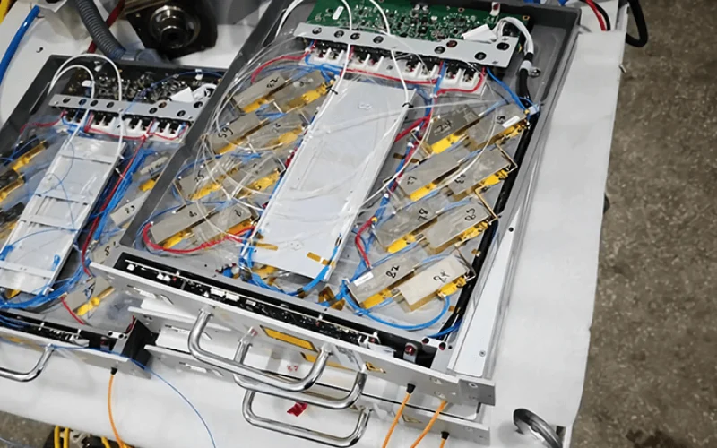
A fiber laser source datasheet should be read as a combination of process capability, optical compatibility, facility requirements, and test evidence—not as a simple power-rating sheet. Start with the operating mode and guaranteed optical output, then verify beam delivery, cooling, electrical, control, and environmental requirements.
This distinction matters because two sources carrying the same kilowatt rating may require different processing heads, chillers, electrical supplies, control interfaces, or machine layouts. A disciplined review prevents buyers from approving a laser that looks suitable on the first page but cannot be integrated into the intended machine.
What Should You Check First on a Fiber Laser Source Datasheet?
First identify the operating mode, rated output power, wavelength, beam-delivery configuration, and intended application. These specifications establish what type of laser you are evaluating and whether the remaining values can be compared with another source.
Begin with the model designation and confirm whether the source operates in continuous-wave, modulated CW, QCW, or pulsed mode. Do not compare their wattage figures without accounting for how the energy is delivered.
- CW: Continuous optical output suitable for processes requiring sustained energy delivery.
- Modulated CW: A CW source whose output can be switched or varied at a specified frequency.
- QCW: High-power pulses with a duty cycle that keeps average power below peak power.
- Pulsed: Energy delivered as individual pulses defined by pulse energy, duration, and repetition rate.
Next, confirm whether the beam is described as single-mode, low-order-mode, or multi-mode. The same rated power can produce different spot sizes, focal tolerances, and energy distributions when the beam quality and delivery fiber are different.
Buyers evaluating continuous-wave fiber laser sources should therefore avoid using output power as the sole screening criterion.
What Does Rated Output Power Actually Mean?
Rated output power is the output level assigned to the product under specified operating and cooling conditions. It should not be treated as the guaranteed minimum output of every delivered unit unless the datasheet, quotation, or acceptance document explicitly defines it that way.
The terminology used by manufacturers is not completely uniform. A datasheet may state nominal power, rated power, typical power, minimum output, maximum output, or simply an “up to” value.
What Is the Difference Between Rated, Nominal, Typical, and Minimum Power?
Rated and nominal values identify the intended product class, while a typical value describes expected rather than guaranteed performance. For procurement, a clearly stated minimum output is usually more useful because it can become an acceptance criterion.
For example, “nominal output power: 3,000 W” does not necessarily mean that every unit must measure at least 3,000 W during final inspection. By contrast, “output power: ≥3,000 W under specified cooling conditions” establishes a measurable lower limit.
Also check the adjustment range. A source rated at 6 kW may operate from 10% to 100% power, while another may specify stable operation from 1% to 100%. The lower control limit can matter during piercing, thin-sheet cutting, tack welding, or process transitions.
The ISO 11554 test framework for laser power, energy, and temporal characteristics shows why a meaningful power specification requires a defined measurement method. The value should be interpreted together with warm-up time, coolant temperature, measurement duration, detector calibration, and uncertainty.
How Should You Compare Average Power, Peak Power, and Pulse Energy?
Average power describes energy delivered over time, while peak power is the highest instantaneous power reached during a pulse. Pulse energy, pulse duration, and repetition rate must be read together because no single value fully describes a pulsed source.
For a regular pulse train, the basic relationship is:
Average power = pulse energy × repetition rate
For a simple pulse shape, peak power can be approximated as:
Peak power ≈ pulse energy ÷ pulse duration
A QCW source may therefore advertise several kilowatts of peak power while delivering much lower average power. That source should not be compared directly with a CW laser based only on the largest wattage printed on the datasheet.
Before comparison, record whether each number refers to continuous power, average pulsed power, maximum peak power, or a short-duration operating condition.
How Do You Read Wavelength and Spectral Specifications?
The wavelength identifies the main spectral region in which the source operates, while tolerance and linewidth describe how tightly the optical output is distributed around that value. These specifications matter when the source must match wavelength-sensitive optics, diagnostics, coatings, or specialized processes.
Industrial ytterbium fiber laser datasheets commonly list wavelengths near the 1 μm region, but one source may state 1,070 nm while another states 1,080 ± 10 nm. These descriptions may overlap, yet they are not automatically interchangeable in every optical system.
Check whether the datasheet provides:
- Central or nominal wavelength
- Permitted wavelength range
- Wavelength tolerance
- Spectral bandwidth or linewidth
- Wavelength stability over temperature or power
For conventional cutting and welding systems, a small wavelength difference may have less practical effect than BPP, core diameter, or process optics. For sensing, coherent combining, narrow-linewidth applications, or wavelength-specific components, the spectral specification may become decisive.
What Do M² and BPP Tell You About Beam Quality?
M² describes how far a real beam departs from an ideal diffraction-limited beam, while beam parameter product combines beam size and divergence into a practical focusability metric. Lower values generally indicate higher brightness, but neither value should be interpreted without wavelength, fiber diameter, beam profile, and measurement conditions.
What Is M² on a Fiber Laser Datasheet?
An ideal Gaussian beam has an M² value of 1, while a real beam has a value of 1 or higher. As M² increases, the beam generally diverges more strongly or produces a larger focused spot than an ideal beam with the same wavelength and optical arrangement.
The internationally recognized ISO 11146-1 method for measuring beam widths, divergence, and beam propagation ratios is important because M² depends on how the beam is measured across its propagation path. A value without a test method, operating power, or tolerance is difficult to use as a contractual comparison.
When reading M², ask:
- Is the number typical or a guaranteed maximum?
- Was it measured at full rated power?
- Was it measured at the source output or after the process fiber?
- Does the supplier provide separate values for both beam axes?
- Does beam quality remain stable across the specified power range?
A source with a typical M² of 1.1 should not automatically be ranked above one with a guaranteed M² of less than 1.3. The first figure may represent selected units or favorable test conditions, while the second establishes an upper acceptance limit.
What Is BPP on a Fiber Laser Datasheet?
Beam parameter product is usually expressed in mm·mrad and represents the product of beam radius and far-field divergence half-angle. It is commonly used for high-power industrial lasers because it helps engineers estimate how effectively the beam can be transported and focused.
For measurements using compatible beam definitions, BPP is related to wavelength and M²:
BPP = M² × wavelength ÷ π
The relationship between BPP, brightness, and fiber coupling explains why a lower BPP can support a smaller delivery core or tighter focus. However, the best process does not always require the smallest possible spot.
A larger beam or different energy distribution may improve tolerance, weld-pool behavior, cladding coverage, or thick-plate cutting. The required beam quality must therefore come from the process objective rather than a general assumption that the lowest number is always superior.
How Does Delivery-Fiber Core Diameter Affect Laser Performance?
The delivery-fiber core diameter affects beam transport, achievable spot size, BPP, and compatibility with the processing head. It must be evaluated together with numerical aperture, collimation optics, focusing optics, and the required energy distribution.
Commercial sources may offer the same nominal power with different delivery-core options. A current industrial datasheet, for example, can pair a 50 μm process fiber with a lower BPP and a 100 μm fiber with a higher BPP, demonstrating that the core configuration is part of the optical specification rather than an accessory detail.
The Coherent guide to fiber beam delivery defines BPP at the delivery-fiber output as a product of core-related beam radius and divergence. It also shows why core size alone cannot predict the final process spot without the downstream optical system.
When reviewing core diameter, verify:
- Whether the value is the active optical core or an outer fiber dimension
- The BPP associated with that specific core option
- The numerical aperture or output divergence, where available
- The connector and processing-head compatibility
- The collimation and focal lengths used by the machine
- Whether the quoted process data was produced with the same configuration
Do not assume that changing from a 100 μm fiber to a 50 μm fiber is a drop-in upgrade. The new configuration may alter focus size, intensity, depth of focus, contamination sensitivity, optical loading, and process-window requirements.
Which Datasheet Specifications Affect Performance, Compatibility, or Installation?
A useful review separates process specifications from integration and facility requirements. The following table identifies what each major value describes and what should be confirmed before approving a source.
| Datasheet specification | What it describes | Why it matters | What the buyer should verify |
|---|---|---|---|
| Rated output power | Continuous or average optical output | Defines available process energy | Minimum guaranteed output and test conditions |
| Peak power | Maximum instantaneous pulse power | Affects pulsed interaction and penetration | Pulse width, pulse shape, and repetition rate |
| Wavelength | Main optical output wavelength | Must suit optics and process requirements | Range, tolerance, and spectral width |
| M² | Departure from ideal beam propagation | Indicates focusability | Maximum value, test method, and measurement power |
| BPP | Beam radius multiplied by divergence | Helps predict beam delivery and focusing | Units, beam definition, and fiber configuration |
| Fiber core diameter | Active delivery-core size | Affects BPP, spot formation, and head compatibility | Core option used for all quoted performance data |
| Output connector | Mechanical and optical termination | Must match the processing head | Exact connector family and interface version |
| Fiber length | Length of the delivery cable | Determines machine routing | Usable length and bending limitations |
| Modulation frequency | Rate at which output can be switched | Affects dynamic process control | Frequency available at full modulation depth |
| Power stability | Output variation over time | Affects process repeatability | Time window, warm-up, and calculation method |
| Cooling requirement | Coolant temperature, flow, and thermal load | Prevents overheating and shutdown | Capacity, flow, pressure, and water specification |
| Input power | Required electrical supply | Determines facility compatibility | Voltage, phase, current, frequency, and connected load |
| Control interface | Connection to the machine controller | Enables commands, monitoring, and alarms | Signal levels, protocol, and documentation |
| Dimensions and weight | Physical source configuration | Affects machine-cabinet design | Clearance, orientation, lifting, and service access |
How Do You Read Modulation Frequency and Power-Control Specifications?
Modulation specifications describe how quickly and accurately the source responds to control commands. A maximum frequency does not necessarily mean the source can deliver full rated power or full modulation depth across the entire listed range.
Check the modulation frequency together with:
- Duty-cycle limits
- Rise and fall times
- Minimum controllable output
- Analog command range
- Digital command resolution
- Power-ramping capability
- Maximum frequency at full modulation depth
For example, a datasheet may state a modulation range extending to several kilohertz but add a note that full-depth modulation is available only within a narrower range. This distinction can affect piercing sequences, corner control, weld starts, and transitions between processing conditions.
The current Coherent EDGE FL datasheet provides a useful example of how operation mode, power range, modulation frequency, BPP, fiber core, cooling, electrical input, and customer interfaces appear as related specifications. A buyer should look for this level of integration detail rather than reviewing the optical power in isolation.
What Does Power Stability Mean on a Fiber Laser Datasheet?
Power stability describes output variation during a defined period and under stated operating conditions. A percentage without a time interval, calculation method, warm-up condition, or measurement setup is not sufficient for a fair comparison.
Two suppliers may both state ±1% stability but use different definitions. One may report peak-to-peak variation over several minutes, while another reports RMS variation over several hours after thermal stabilization.
Ask the supplier to clarify:
- Whether the value is RMS, standard deviation, or peak-to-peak
- The measurement duration and sampling rate
- The power setting used for the test
- The required warm-up time
- The coolant and ambient-temperature limits
- Whether the result is typical or guaranteed
- Whether the report applies to the model or the delivered serial number
The NIST guidance on CW laser power and energy calibration explains the importance of calibrated detectors, traceability, calibration factors, and measurement uncertainty. This means that a power result should never be treated as an exact value independent of the measurement system used to obtain it.
How Do You Check the Output Connector and Delivery Fiber?
The output connector and delivery fiber form the physical and optical interface between the source and processing head. An incompatible connector, core diameter, fiber length, or interlock arrangement can prevent installation even when the power rating is correct.
What Do QBH, QD, and QCS Connectors Mean?
QBH, QD, QCS, and similar terms identify connector families used to connect high-power delivery fibers to downstream optical systems. Buyers should confirm the precise interface rather than accepting a general description such as “standard connector.”
A processing head described as QBH-compatible may still require confirmation of mechanical dimensions, optical configuration, safety interlocks, cooling, protective components, and permissible power. Obtain written compatibility confirmation from both the source supplier and processing-head supplier.
Also confirm whether the connector contains replaceable protective components, whether servicing can be performed locally, and what contamination-control procedure is required during installation.
What Fiber Length and Bending Radius Do You Need?
The delivery fiber must be long enough to follow the complete machine route without tension, twisting, or excessive bending. Additional length can provide installation flexibility, but unmanaged excess cable also increases handling and damage risk.
Review the machine layout before ordering and confirm:
- Nominal fiber length and manufacturing tolerance
- Static and dynamic minimum bending radii
- Routing through cable carriers or moving axes
- Permitted torsion and pulling load
- Connector-protection requirements
- Whether the process fiber is field-replaceable
Do not route a high-power delivery fiber according to ordinary electrical-cable practices. The fiber is part of the optical system, and damage can cause output loss, localized heating, alarms, or catastrophic failure.
How Do You Read Cooling Requirements?
Cooling specifications define the thermal conditions required for stable operation. A chiller chosen only by nominal cooling capacity may still be unsuitable if it cannot provide the required flow, pressure, temperature stability, or coolant quality.
What Cooling Capacity and Flow Rate Does the Laser Source Require?
The chiller must remove the thermal load while maintaining the source within its specified inlet-temperature range. Confirm whether the listed cooling requirement covers only the laser source or also includes the processing head and other optical components.
A complete cooling review should include:
- Recommended cooling capacity
- Minimum coolant flow
- Permitted inlet temperature
- Temperature stability
- Maximum pressure and pressure drop
- Hose and fitting dimensions
- Separate circuits for the source and processing head
- Ambient-temperature and condensation limits
Some industrial laser datasheets specify coolant temperatures in a defined range and explicitly require non-condensing operation. This warning is important because selecting a very low water temperature can create condensation when ambient humidity is high.
What Water Quality Should the Datasheet Specify?
Coolant quality can affect scaling, corrosion, biological growth, conductivity, and long-term reliability. The operating manual should identify the approved coolant and maintenance limits rather than merely stating “use clean water.”
Request the complete cooling specification, including permitted conductivity, filtration level, chloride or mineral restrictions, biocide guidance, antifreeze restrictions, and replacement intervals. Do not substitute local tap water, automotive coolant, or an unapproved additive without written authorization.
If the short commercial datasheet omits water-quality requirements, treat the installation manual as required documentation before chiller selection.
Which Electrical Specifications Must Match Your Facility?
The electrical section should state supply voltage, tolerance, phase, frequency, maximum current, power consumption, and connected load. These values determine whether the source can be safely installed at the destination facility.
Do not assume that all sources of the same output power use the same input supply. One model may accept single-phase power, while a higher-power configuration may require a wide-range three-phase supply.
Check:
- Nominal input voltage and tolerance
- Single-phase or three-phase connection
- Grid frequency
- Maximum operating current
- Power consumption at rated output
- Connected load in kVA
- Protective-earth requirements
- Circuit-breaker and cable recommendations
- Inrush current
- Need for voltage stabilization or power conditioning
Remember to calculate the complete machine load, including the laser source, chiller, motion system, extraction equipment, compressor, processing head, and auxiliary systems. The source datasheet covers only one part of the installation.
Which Control and Communication Interfaces Should You Verify?
Control specifications define how the machine enables emission, commands output power, reads alarms, and monitors operating status. Compatibility must be confirmed at the signal and protocol level rather than inferred from a statement that the source supports remote control.
The required information may include:
- Laser-enable and emission-enable inputs
- Ready, warning, and alarm outputs
- Safety-interlock circuits
- Analog power command range
- Digital power-setting method
- RS-232, RS-485, CAN, or Ethernet communication
- Fieldbus options such as EtherCAT
- Alarm codes and diagnostic registers
- Remote-service access
An Ethernet port does not prove that two systems use the same protocol. Request the interface manual, connector pinout, signal-voltage definitions, command structure, timing requirements, and alarm list before software development begins.
For replacement projects, compare every input and output rather than assuming that an adapter cable is sufficient. Differences in logic levels, enable sequences, alarm behavior, or analog scaling may require changes to the machine controller.
How Do You Check Mechanical and Environmental Requirements?
Dimensions and weight determine whether the source fits the machine, while environmental limits determine whether it can operate reliably after installation. Service clearance, ventilation, humidity, altitude, dust, and condensation can be as important as cabinet dimensions.
Review:
- Overall dimensions and connector projection
- Weight and lifting points
- Permitted mounting orientation
- Ventilation and maintenance clearance
- Ambient operating-temperature range
- Storage and transport temperature
- Relative-humidity limit
- Non-condensing requirement
- Maximum operating altitude
- Dust, vibration, and shock limits
- Ingress-protection rating, where specified
A source may fit inside the cabinet but still be incorrectly integrated if filters, service panels, coolant connections, or the delivery fiber cannot be accessed. Review the dimensional drawing rather than relying only on the three external measurements in the product table.
What Does the Laser Safety Class Tell You?
Laser class describes the potential hazard associated with accessible laser radiation under defined conditions. It does not measure beam quality, efficiency, reliability, processing performance, or the compliance status of the complete machine.
IEC 60825-1 covers laser-product classification and safety requirements for products emitting laser radiation within its stated wavelength scope. High-power industrial systems commonly require engineering controls such as protective enclosures, interlocks, warning systems, and controlled access.
Check the classification and labeling of the supplied source, but do not assume that integrating a classified source automatically classifies or certifies the finished machine. The system integrator must evaluate accessible radiation, enclosure design, viewing paths, maintenance modes, interlocks, and foreseeable fault conditions at machine level.
Similarly, a conformity mark or declaration for the source does not automatically extend to the completed cutting, welding, or additive-manufacturing system.
How Can You Tell Whether a Datasheet Value Is Guaranteed?
A useful specification identifies the value, limit, test method, and conditions under which it applies. Terms such as “typical,” “reference,” “up to,” or “configuration-dependent” should not be converted into acceptance criteria without additional written confirmation.
For every critical value, look for four elements:
- Definition: What exactly is being measured?
- Limit: Is it a minimum, maximum, range, or typical result?
- Condition: At what power, temperature, and operating state does it apply?
- Evidence: Which test report confirms the delivered unit meets it?
Measurement uncertainty should also be considered. The NIST publication on CW laser power and energy calibrations describes calibration factors and uncertainty assessments as part of a valid result. A measured value of 3,010 W is not meaningfully different from 3,000 W unless the measurement uncertainty and acceptance rule are known.
Do not use brochure statements as the only basis for final approval. Transfer critical requirements into the purchase specification, quotation, technical agreement, or FAT protocol.
What Information Should You Request If It Is Missing from the Datasheet?
A short commercial datasheet may be sufficient for initial screening but insufficient for machine integration. Before ordering, request the documents needed to verify optical, mechanical, electrical, cooling, control, safety, and service requirements.
The document package should normally include:
- Complete technical or installation manual
- Dimensional drawing
- Delivery-fiber and connector specification
- Minimum bending-radius requirements
- Cooling and water-quality specification
- Electrical connection requirements
- Interface manual and pinout
- Alarm-code and troubleshooting list
- Maintenance schedule
- Warranty terms and exclusions
- Compliance documents
- Output-power and stability test report
- Beam-quality report when M² or BPP is contractual
- Burn-in or aging-test record
Also request confirmation that the quoted fiber core, connector, cable length, interface version, and cooling configuration are the same ones that will be delivered. Optional configurations can change several lines of the datasheet at once.
How Do You Compare Two Fiber Laser Source Datasheets Correctly?
Compare values only when both suppliers use equivalent definitions, operating modes, units, and measurement conditions. The source with the highest stated power is not necessarily the better choice if its beam delivery, control system, cooling requirements, or guaranteed limits do not match the machine.
Use the following sequence:
- Confirm that both products use the same operating mode.
- Separate nominal, typical, minimum, and maximum power values.
- Compare wavelength and spectral requirements.
- Compare M² or BPP under equivalent conditions.
- Match fiber core diameter and output connector.
- Confirm delivery-fiber length and routing limits.
- Compare modulation range, response, and power control.
- Compare stability definitions and test periods.
- Verify chiller, electrical, and environmental requirements.
- Confirm controller signals and communication protocols.
- Separate guaranteed specifications from typical values.
- Request serial-specific acceptance evidence.
A comparison sheet should include a fifth column called “unresolved.” Any item in that column should be closed by written supplier confirmation before the model is approved.
When comparing CW laser source configurations, record the exact power, beam-delivery, connector, fiber, cooling, and interface combination rather than comparing only the product-family names.
What Should Be Verified During Fiber Laser Source Acceptance Testing?
Acceptance testing should confirm that the delivered unit matches the ordered configuration and meets the agreed performance limits. The report should identify the serial number, test conditions, measurement equipment, results, tolerances, and pass/fail criteria.
A practical FAT checklist can include:
- Model and serial number
- Rated and measured output power
- Power-adjustment range
- Short-term or long-term power stability
- Output wavelength
- M² or BPP when contractually specified
- Delivery-fiber core diameter
- Connector type and fiber length
- Modulation and power-command response
- Alarm and interlock operation
- Cooling flow and temperature
- Electrical input and power consumption
- Burn-in duration
- Visual inspection and connector condition
- Packaging and transport protection
The test procedure should use the applicable measurement methods agreed during procurement. ISO 11554 provides methods for laser radiant power, energy, temporal characteristics, and stability, while ISO 11146 addresses beam-width, divergence, and beam-propagation measurements.
A model-level datasheet establishes the expected specification. A serial-specific FAT report provides evidence about the actual unit being shipped.
What Is the Quickest Way to Review a Fiber Laser Source Datasheet?
A fast review should answer four questions: Can the source perform the process, can it connect to the optical system, can the facility support it, and can the supplier prove the stated performance? Any unanswered item should be resolved before the model is approved.
- Is the operating mode suitable?
- Is output power guaranteed or only typical?
- Are average and peak power clearly separated?
- Are M² or BPP properly defined?
- Does the delivery-fiber core suit the process head?
- Does the connector match the intended optics?
- Is the fiber length sufficient for the machine layout?
- Are modulation and control limits suitable?
- Can the chiller meet the thermal and water requirements?
- Does the facility provide the correct electrical supply?
- Are the controller interfaces fully documented?
- Are environmental restrictions acceptable?
- Is the safety classification clearly stated?
- Are test conditions and tolerances defined?
- Will the supplier provide serial-specific acceptance records?
The most reliable datasheet is not necessarily the one containing the largest number of specifications. It is the one that clearly distinguishes guaranteed performance, configuration-dependent values, integration requirements, and the evidence available for the delivered unit.
Frequently Asked Questions About Fiber Laser Source Datasheets
Is Higher Fiber Laser Source Power Always Better?
No. Higher power is useful only when the beam delivery, processing head, cooling system, machine structure, and target process can use it effectively.
Is a Lower BPP Always Better?
A lower BPP generally supports tighter focusing and higher brightness. Some welding, cladding, and thick-material processes may instead benefit from a larger spot, different beam profile, or greater focal tolerance.
Can Two Laser Sources with the Same Rated Power Be Interchanged?
Not automatically. Core diameter, BPP, connector, fiber length, control signals, cooling requirements, electrical input, and physical dimensions must all be checked.
What Is the Most Important Missing Datasheet Document to Request?
The most useful package is usually the full technical manual combined with a serial-specific acceptance report. The manual establishes integration requirements, while the report confirms the performance and configuration of the delivered unit.