
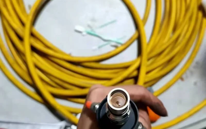
Fiber laser sources have a reputation for being low-maintenance — and relative to CO₂ lasers, that reputation is earned. But “low maintenance” is not “no maintenance,” and the maintenance that does matter is frequently misunderstood. Most maintenance guides conflate the laser source with the entire machine, leaving operators uncertain about which tasks protect the source specifically, which tasks belong to a technician, and what the early warning signs of source trouble actually look like. This guide draws those distinctions clearly.
The most important thing to understand about fiber laser source maintenance
The fiber laser source itself — the sealed module containing the pump diodes, gain fiber, and beam delivery optics — is not something a machine operator maintains directly. Unlike CO₂ lasers that have optical beam paths requiring mirror alignment, lens cleaning, and gas management, fiber lasers deliver the beam through a sealed fiber optic cable with no mirrors or alignment points accessible to the operator. The source enclosure is a factory-sealed precision instrument; opening it voids the warranty and risks permanent damage to internal components that require specialized equipment and training to handle safely.
What operators do maintain are the three systems that support the source’s correct operation: the cooling circuit that controls the pump diode operating temperature, the delivery fiber connector interface between source and cutting head, and the electrical environment (cabinet ventilation, power supply conditions) in which the source operates. Every task in this guide falls into one of these three categories. Understanding this framework makes the maintenance schedule logical rather than arbitrary — each task protects a specific variable that the source’s long-term performance depends on.
What can a machine operator safely do — and what must stay with a technician?
The boundary between operator maintenance and technician maintenance exists for two reasons: warranty protection and safety. Crossing it does not demonstrate competence — it voids warranty coverage on a component that costs thousands of dollars to replace, and it can create safety hazards in a high-voltage, high-optical-power system.
When Trumpf sells a machine, it provides operator training that covers proper daily maintenance. The accompanying manual provides all maintenance check points, and TRUMPF provides a list of maintenance tools the operator will need — including a water conductivity meter and optical paper for spot image tests. The explicit inclusion of these specific tools in operator training is informative: they define the boundary of what operators are expected to do independently.
| Task | Who performs it | Frequency | Consequence if done incorrectly |
|---|---|---|---|
| Chiller temperature and coolant level check | Operator | Daily | Undetected cooling failure → thermal damage |
| Delivery fiber connector visual inspection | Operator | Daily | Undetected mechanical damage → back reflection event |
| Source status / fault code check | Operator | Daily | Running with uncleared fault → compounding damage |
| Fiber connector end-face cleaning | Operator (trained) | Weekly | Incorrect technique → end-face scratching |
| Electrical cabinet fan inspection | Operator | Weekly | Undetected fan failure → electronic overheating |
| Coolant visual and conductivity check | Operator | Monthly | Degraded coolant → scaling, corrosion, electrical risk |
| Coolant replacement | Operator | Every 1–3 months | Deferred replacement → coolant contamination |
| Electrical cabinet interior cleaning | Operator (vacuum only) | Every 3 months | Compressed air use → conductive dust on circuit boards |
| Output power baseline check | Operator (with documentation) | Monthly | No trending → degradation goes undetected |
| Full optical performance verification | Qualified technician | Annually | N/A — operator should not attempt this |
| Internal source inspection or adjustment | Qualified technician only | As needed | Warranty void; risk of permanent source damage |
| Firmware or drive current adjustment | Qualified technician only | As needed | Incorrect settings → accelerated diode degradation |
| Delivery fiber replacement | Qualified technician only | As needed | Incorrect fusion or connector work → beam quality loss |
Daily checks: what to verify before each production shift
Daily checks take five to ten minutes and protect against the failure modes most likely to develop overnight or between shifts — cooling system changes, connector disturbance from the previous shift’s handling, and fault codes from the last production run.
Chiller temperature and coolant level — the five-minute check that protects the most expensive component
Before starting the first job of the shift, confirm that the chiller is running, its display shows the correct setpoint temperature, and the coolant level is within the marked range on the reservoir. These two checks take under a minute and directly verify the cooling condition that governs source temperature — the single most important variable in pump diode lifespan, as covered in the context of fiber laser source thermal management.
A chiller that has developed a coolant leak overnight will show a low level reading before it shows a temperature alarm — catching the level drop early allows a controlled response rather than an emergency shutdown mid-production. If the chiller display shows a temperature reading significantly above setpoint at startup, before the source has begun generating heat, investigate before starting production: the chiller may have developed a fault during idle time.
Delivery fiber connector visual check — the maintenance task nobody mentions
The QBH or QD connector where the delivery fiber connects to the cutting head is the most mechanically vulnerable point in the laser source’s beam delivery path, and it is the maintenance check most conspicuously absent from standard fiber laser maintenance guides.
Before each shift, visually inspect the connector housing for mechanical damage — cracks, bent locking rings, or impact marks. Verify that the connector is fully seated and locked according to the machine manufacturer’s specification. Check that the fiber cable has not been kinked, pinched, or bent tighter than its minimum bend radius specification at any point between the source and the cutting head. Always power off before checking fiber cables. A loose or damaged connector can cause localized heating at the connection point, back reflection events, and beam quality degradation — all of which appear as cutting performance problems before they trigger any source fault code.
Source status indicators and fault codes — read before you cut
Check the source’s status indicators on the machine HMI or the source’s own control panel before starting production. Do not clear fault codes without understanding what triggered them — a fault code that appears, gets cleared, and reappears is telling you something the source’s protection system has detected. Many modern fiber lasers provide diagnostic alerts that identify developing issues before they become serious failures — these alerts are actionable early warnings, not annoyances to dismiss. If a fault code cannot be explained and cleared with confidence, contact the machine manufacturer’s technical support before running production. TRUMPF’s service team reports an 80% success rate resolving issues over the phone — most source fault codes have a known cause and a defined response procedure.
Weekly checks: what to inspect and clean every 5–7 days
Weekly tasks address slower-developing conditions — connector end-face contamination that builds up through normal cutting operations, cooling fan performance, and coolant condition changes that are not visible in daily level checks.
Fiber connector end-face inspection and cleaning
Connector end-face contamination is one of the most common operator-addressable causes of localized heating and back reflection sensitivity, and it is almost entirely absent from standard maintenance guides despite being a task operators can safely perform with basic training.
The correct procedure: power down the source completely before disconnecting the connector. Remove the connector from the cutting head and inspect the end-face under bright light or a loupe for black spots, haze, or visible particulates. If contamination is present, clean using a lint-free, optical-grade wipe moistened with ≥99% isopropyl alcohol (IPA). Wipe in a single direction — do not scrub back and forth. Allow to dry fully before reconnecting. Inspect first and clean only when needed — excessive cleaning can scratch optics. Never use general-purpose cleaners, compressed air, or cloth that could leave fibers on the end-face.
A connector end-face that shows a black spot that cannot be removed by standard cleaning, or that shows physical damage (chips, cracks, pit marks), requires technician assessment — do not continue operating with a visibly damaged connector end-face.
Electrical cabinet fan inspection
The electrical cabinet housing the source’s drive electronics and control boards depends on forced-air cooling from fans to prevent overheating. Once per week, verify that every fan on the source’s electrical cabinet is spinning freely and at normal speed — a fan running slowly or intermittently is about to fail, and a failed fan can allow cabinet temperatures to rise to levels that damage electronics independently of the liquid cooling circuit. Fan inspection and dust removal are critical because heat and dust kill electronics.
Listen as well as look: a fan bearing that is developing a fault will often produce a faint grinding or rattling sound before it fails completely. A fan producing any unusual noise should be flagged for replacement at the next scheduled maintenance window rather than left until it stops.
Coolant visual inspection — color, clarity, and odor
In addition to the daily level check, perform a weekly visual assessment of the coolant itself. Draw a small sample in a clean clear container and hold it against a white background. Normal coolant should be clear and colorless (or the manufacturer’s specified color if an additive has been used), free of visible particles, and without any musty or chemical odor.
Cloudiness or color change indicates either microbial growth or metal ion contamination from corrosion within the cooling circuit — both require immediate coolant replacement, not just top-up. An unusual odor, particularly musty or sulfurous, indicates biological contamination. These conditions degrade cooling efficiency, promote further corrosion, and in deionized water systems, change the electrical conductivity properties that make DI water a safer coolant than tap water.
Monthly and quarterly tasks: scheduled maintenance for the source’s support systems
Monthly and quarterly tasks are the ones most often deferred because they feel less urgent than daily checks — and they are precisely the ones that matter most for long-term source health, because the conditions they address develop slowly and invisibly.
Coolant replacement schedule — why “when it looks dirty” is too late
Replace coolant every 1–3 months depending on usage frequency and climate conditions. The visual threshold — “replace it when it looks dirty” — is not early enough, because the conditions that degrade coolant performance develop before they are visible. Electrical conductivity rises as ions accumulate in the coolant from normal system interaction; this rise precedes visible discoloration, and elevated conductivity in a system with DI water requirements represents a direct increase in electrical safety risk if a pinhole leak develops near high-voltage components.
TRUMPF operators are equipped with a water conductivity meter as a standard maintenance tool — not because checking water with a meter is difficult, but because it is the only reliable way to assess coolant condition before the degradation has progressed far enough to show visually. Establish a conductivity baseline for your system’s fresh coolant at installation, and replace when measured conductivity has drifted meaningfully from that baseline, regardless of whether the coolant looks clean.
Quarterly coolant replacement costs approximately $100–150 in materials — a fraction of the cost of accelerated source degradation from operating with compromised coolant over an extended period.
Electrical cabinet interior cleaning — why you vacuum, not blow
Every three months, clean the interior of the source’s electrical cabinet to remove accumulated dust. The critical technique requirement: use a vacuum cleaner, not compressed air. Compressed air blows conductive metal dust — present in any fabrication environment — into circuit boards and onto component contacts, where it can cause short circuits or intermittent electrical faults. A vacuum draws that same dust out and away from the electronics.
Work methodically around heat sinks, drive boards, and any accessible filter screens, paying particular attention to areas where airflow is concentrated. Do not touch circuit boards, connectors, or component leads during this process. If the cabinet shows significant dust accumulation between quarterly cleanings — a sign that the facility environment has heavier particulate levels than typical — shorten the cleaning interval to monthly.
Coolant resistivity check for deionized water systems
For systems specifying deionized water as coolant, monthly resistivity measurement is essential maintenance, not optional. DI water requires DI-compatible materials and a deionization cartridge to maintain the required resistivity level — and that cartridge has a finite service life that is not visible from the outside.
Measure coolant resistivity monthly using a calibrated conductivity/resistivity meter. The target range for most fiber laser source cooling systems is 1–3 MΩ·cm; consult your source manufacturer’s documentation for the exact specification, as some systems have tighter requirements. When resistivity drops below the specified minimum, replace the deionization cartridge — do not simply top up the system with fresh DI water, as this dilutes rather than restores the full circuit’s water quality. Confirm that the replacement cartridge is rated for the materials in your specific cooling circuit.
How to track laser source output power as an early degradation indicator
Every maintenance guide in this space is organized around reactive cleaning and inspection. The most valuable proactive maintenance practice for the laser source specifically — one that appears in none of the standard checklists — is systematic output power tracking over time.
Fiber laser source modules are typically rated for 100,000 operational hours, with gradual power degradation beginning around 70,000–80,000 hours under normal operating conditions. But degradation that begins later in source life is not the only pattern — sources operating under suboptimal thermal conditions or inconsistent maintenance degrade faster and earlier than this benchmark suggests. The only way to know where your specific source sits on this curve is to measure.
The practical implementation: establish a baseline output power measurement at commissioning or the start of a new source. Record actual measured output power against the source’s rated specification monthly, using the source’s built-in power monitoring function or an external power meter if available. Log the date, operating hours at measurement, and the measured value. Plot these readings over time.
A source tracking flat or within a few percent of its commissioning baseline is performing as expected. A source showing a consistent downward trend steeper than the expected gradual degradation curve warrants investigation — it may indicate a cooling issue, a back reflection event history, or current overdrive that is accelerating pump diode aging faster than rated conditions predict. Catching this trend at 5–10% power loss gives you time to investigate and address the root cause; waiting until cutting quality has noticeably degraded means the underlying condition has been running unchecked for months. This monitoring approach directly supports the resale value documentation framework covered in our guide to fiber laser source lifespan.
Assist gas quality: why it matters for source protection, not just cut quality
The first and most critical variable in fiber laser maintenance is the quality of the assist gas — it must be contamination free. This is TRUMPF’s technical support manager’s direct statement, and it reflects a source protection consideration that most operators associate only with cut quality.
The reason assist gas quality affects the source is the direction contaminants travel. Moisture, oil aerosol from an improperly maintained air compressor, and particulates in the gas supply travel through the cutting head and can reach the delivery fiber connector and the optical interface between source and cutting head. Over time, oil contamination on optical surfaces causes absorption of laser energy at the surface — producing localized heating that damages the optics and, in severe cases, the connector end-face. Moisture promotes biological and chemical contamination in the optical path.
Practical requirements: ensure your oxygen or nitrogen supply lines are free of moisture and oil before they reach the cutting head. If you use an on-site air compressor for compressed air assist, verify the inline oil-water separator and desiccant dryer are serviced on schedule — these are the components that prevent compressor oil from reaching the laser optics. For nitrogen and oxygen from cylinders or bulk supply, verify gas purity specification: industrial-grade purity (99.5% or above for nitrogen, higher for stainless steel cutting with tight edge quality requirements) is the appropriate standard for laser cutting applications.
Common warning signs that the laser source needs attention
These signs do not always indicate source failure — many have maintenance-addressable causes. But each warrants investigation before continuing heavy production.
Unstable output power during cutting. Power fluctuations that were not present previously, visible as inconsistent cut depth or edge quality across a single job, can indicate a connector contamination issue, a cooling system problem causing thermal instability, or the onset of pump diode degradation. Start with connector inspection and coolant condition before assuming a source hardware fault.
Needing higher power settings to achieve the same cut result. If parameters that previously cut a given material cleanly now require power increases to produce the same result, the source’s effective output at a given command level has declined — consistent with the gradual degradation pattern described by the MTBF framework. Document the change and note it in your output power log.
Increasing frequency of thermal protection faults. A source that is shutting down on thermal protection more frequently than it did previously, without a change in production intensity, indicates that the cooling system’s ability to manage the thermal load has degraded. Check coolant level, chiller performance, and the cooling channels for scaling-related flow restriction before attributing the fault to the source itself.
Fault codes that recur after clearing. A fault code that clears and immediately or repeatedly reappears is the source’s protection system detecting a condition it cannot self-resolve. Do not continue clearing and running. Contact the machine manufacturer’s technical support with the specific fault code and its frequency — in many cases this is diagnosable remotely.
Annual source inspection: what it involves and when to schedule it
Annual inspection of the laser source should be performed by the machine manufacturer’s service team or a qualified technician — not by the machine operator, regardless of the operator’s experience level. The tasks involved require specialized optical measurement equipment, access to source internals, and calibration data specific to the source model.
Annual major maintenance for fiber laser systems typically includes laser source inspection, full optics verification, and servo system calibration, and should be scheduled during planned production shutdowns such as holidays or inventory periods. It typically requires 2–3 days for a fiber laser system. Scheduling this during a predictable low-demand period means the downtime is absorbed into planned non-production time rather than interrupting a production schedule.
What the annual inspection typically covers: comprehensive output power and beam quality measurement against the source’s rated specifications; inspection of internal fiber splices and connectors accessible to the technician; verification of drive current and control parameter settings against the manufacturer’s calibration standards; and any firmware updates or parameter adjustments published by the source manufacturer since the previous service visit. The output of the inspection — a service report with measured values — should be retained in the machine’s maintenance log. This documentation directly contributes to the source’s provable condition history, which affects both the machine’s ongoing warranty standing and its eventual resale value.
FAQ
Can I open the fiber laser source housing to clean or inspect it myself? No — and this is not a matter of skill level. The fiber laser source housing is a factory-sealed precision optical and electrical assembly. Opening it voids the manufacturer’s warranty, eliminates the protective seal that keeps the internal optical components free of contamination, and exposes high-voltage electrical components that require qualified personnel to work around safely. The maintenance tasks in this guide that operators can safely perform are all external to the source housing — cooling system, connector interface, and electrical cabinet ventilation. Internal source inspection and service are technician tasks without exception.
How do I know if my delivery fiber connector is contaminated? Inspect the connector end-face visually when the fiber is disconnected from the cutting head, using good lighting or a loupe. Black spots, brownish discoloration, haze, or visible particulates on the end-face are contamination indicators. Functionally, connector contamination often shows up first as inconsistent cutting quality on jobs that previously ran without variation, or as increased frequency of back reflection protection events on materials that did not previously trigger them. If visual inspection reveals contamination, clean the end-face using the IPA and lint-free optical wipe procedure described in the weekly maintenance section.
What happens if I run the laser source with low coolant level? A low coolant level reduces the cooling circuit’s thermal mass and can reduce coolant flow rate, both of which allow the source’s operating temperature to rise above its design point. As covered in the thermal management guide, even modest temperature increases above the rated operating range accelerate pump diode degradation through thermally activated mechanisms — meaning that running repeatedly with low coolant is not a benign oversight, it is a condition that shortens the source’s realistic service life. Most sources have a low-coolant alarm that triggers a protective shutdown before temperature reaches a damaging level, but that shutdown is itself a production interruption that a daily level check would have prevented.
How often should I replace the coolant in my fiber laser chiller? Every 1–3 months, depending on usage intensity and climate — with the shorter interval applying to machines running multiple shifts daily in warm, humid environments, and the longer interval applying to lighter single-shift use in climate-controlled facilities. For deionized water systems, use monthly resistivity measurement to determine replacement timing rather than the calendar interval alone — the resistivity reading is a direct measurement of the coolant’s actual condition rather than an estimate based on elapsed time. Never defer coolant replacement based on the coolant’s visual appearance alone; electrical conductivity rises before visible degradation occurs.