
Most fiber laser source guides are written for flat sheet cutting. Tube and pipe cutting uses the same fundamental technology, but it places a distinct set of demands on the laser source — demands that are rarely documented in one place. This guide covers the power requirements, dynamic response characteristics, weld seam handling, open profile challenges, and material-specific source specifications that matter specifically for tube and pipe cutting applications.
Why tube cutting places different demands on the laser source than flat sheet cutting
Flat sheet cutting is, in process terms, relatively uniform: the material is stationary, the thickness is consistent across the sheet, and the cutting head moves in two axes over a flat surface. The laser source operates at a steady power level for extended periods, with relatively infrequent transitions between piercing and cutting modes.
Tube and pipe cutting is structurally different in every one of these respects. The workpiece rotates on a chuck while simultaneously advancing along a linear axis — two motion systems that must be synchronized with the laser source in real time. The material geometry changes continuously: a round tube presents a curved surface to the cutting head, a square tube alternates between flat faces and sharp corners, and an open profile like angle iron or channel steel periodically presents no material at all. Meticulous management of acceleration and deceleration is necessary while maintaining the tube’s stability during cutting, particularly for tubes with weld seams, irregular thicknesses, or complex geometries requiring tilt-head 3D cutting.
These differences mean that tube cutting is a more demanding environment for the laser source’s dynamic response, power modulation capability, and back reflection tolerance — even though the raw power levels involved are often lower than sheet cutting. Understanding why requires looking at each requirement in turn.
Power requirements: why tube cutting uses less power than you might expect
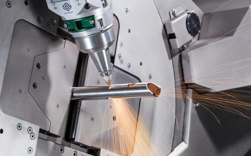
The relationship between wall thickness and required power
The power required to cut a tube is determined by its wall thickness, not its outer diameter. A 200 mm diameter round tube with a 3 mm wall requires the same source power as a 50 mm square tube with a 3 mm wall — the outer geometry affects machine capacity (chuck size, weight per meter), but the source only sees the wall thickness at the cut zone.
Most tube lasers are equipped with sources delivering 2 to 4 kW of cutting power. This is sufficient to cut the typical maximum thickness of mild steel tubing — approximately 8 mm wall — and the typical maximum thickness of aluminum and stainless steel tubing — approximately 6 mm wall — efficiently. The 4 kW configuration at the upper end of this range handles stainless steel and aluminum tubes that require more power per unit thickness than mild steel.
This power range — substantially lower than the 6–12 kW common in flat sheet cutting machines — reflects the actual wall thickness distribution of the tube and pipe products used in most industrial applications: structural hollow sections, HVAC components, furniture frames, automotive exhaust systems, and agricultural equipment all fall predominantly in the 1–6 mm wall thickness range.
Why rotating motion changes the thermal dynamics of cutting
The rotational motion of tube cutting changes the thermal environment at the cut zone in ways that reduce the power density required compared to equivalent-thickness flat sheet cutting.
On a flat sheet, the laser beam enters a stationary workpiece, and heat conducted laterally into the material must be managed entirely by cutting speed and assist gas flow. On a rotating tube, the curved geometry means that the molten metal at the kerf wall faces a different gravitational and centrifugal condition than flat sheet — the combination of tube curvature and rotational motion assists in evacuating molten material from the kerf more effectively than gravity alone on a flat surface. The result is that tube cutting achieves effective penetration at somewhat lower power densities than flat sheet cutting of the same wall thickness.
This explains a pattern that surprises many buyers: a 4 kW tube laser can process material thicknesses that would require 6 kW or more on a flat sheet machine. The thermal dynamics are genuinely different, not just a matter of machine design.
When tube cutting does require higher power
The 2–4 kW standard range has clear exceptions. Three conditions push tube cutting source requirements toward higher power:
Thick-wall structural sections: Heavy-wall tube used in construction, oil and gas, and mining applications — wall thickness above 8–10 mm — requires source power approaching flat sheet cutting levels for the same material type. For carbon steel structural hollow sections above 10 mm wall, 6 kW+ sources become necessary for competitive cutting speeds.
Highly reflective materials: Aluminum and exotic alloys require high-power fiber lasers at 6 kW and above, back-reflection protection, slower cutting speeds, and wider tolerances compared to carbon and stainless steel. The reflectivity of aluminum demands more power to establish a stable keyhole, independent of wall thickness.
Open profiles with heavy flanges: H-beams, wide-flange sections, and heavy channel steel have flange and web thicknesses that can exceed 10–15 mm in structural grades. Cutting these profiles with a tube laser requires source power matched to the thickest cross-section, not the average wall thickness.
| Material | Wall thickness range | Recommended source power | Assist gas |
|---|---|---|---|
| Carbon steel (mild) | 1–6 mm | 1.5–3 kW | Oxygen |
| Carbon steel (mild) | 6–10 mm | 3–4 kW | Oxygen |
| Carbon steel (mild) | > 10 mm | 4–6 kW+ | Oxygen |
| Stainless steel | 1–4 mm | 2–3 kW | Nitrogen |
| Stainless steel | 4–8 mm | 3–4 kW | Nitrogen |
| Aluminum alloy | 1–4 mm | 3–4 kW + back reflection protection | Nitrogen |
| Aluminum alloy | 4–8 mm | 6 kW+ + back reflection protection | Nitrogen |
| Copper / brass | 1–3 mm | 3–4 kW + back reflection protection | Nitrogen |
| Open profiles (angle, channel, H-beam) | Flange/web to 12 mm | 4–6 kW+ depending on cross-section | Oxygen or Nitrogen |
Dynamic power modulation: the most underrated source requirement in tube cutting
Why tube cutting is dynamically different from sheet cutting
The primary modes of acceleration and deceleration in tube lasers are the rotational axis and horizontal movements of the spindles — meticulous management of these within shorter beam-on durations is necessary while maintaining tube stability. Every time the rotational axis decelerates into a corner, reverses direction, or transitions from rotational to linear motion, the effective cutting speed at the material surface changes. If the source power does not change proportionally and immediately, the result is either over-burning at the deceleration point or incomplete cutting at the acceleration point.
Sheet cutting faces similar corner deceleration challenges, but they are less severe for two reasons: the motion dynamics involve only two linear axes rather than the combined rotational and linear motion of tube cutting, and the beam-on durations between corners are typically much longer on a flat sheet job, giving the source more time at steady state between transients.
Tube cutting programs are dense with short-arc segments, tight-radius features, and frequent piercing cycles — a single tube end-face pattern for a structural connection can involve dozens of pierce-and-cut cycles within a few seconds of machine time. More advanced tube lasers address these complexities by monitoring thermal output thresholds and dynamically modulating the piercing power, laser power, frequency, gas pressure, and duty cycle in response. The source must be capable of responding to these modulation commands fast enough to track the motion system.
What “power modulation capability” means on a source datasheet
The source specifications relevant to dynamic tube cutting performance are rise time, fall time, and modulation bandwidth — parameters that describe how quickly the source can change its output power level in response to a command from the CNC controller.
Rise time is the time required for the source to reach full rated power from standby or low-power state. A source with a 1 ms rise time can follow faster power ramps than one with a 5 ms rise time — the difference is visible in corner quality and piercing transition smoothness.
Fall time is the corresponding metric for power reduction. In tube cutting, fast fall time matters at corner deceleration points: the source must reduce power as the rotational axis slows, then restore it as acceleration resumes, within the time window defined by the corner geometry and cutting speed.
Modulation bandwidth describes the maximum frequency at which the source can cycle between power levels. For tube cutting with tight features and frequent pierce-cut transitions, higher modulation bandwidth gives the machine more freedom to program aggressive cutting strategies without running into source response limitations.
When evaluating sources for tube cutting applications, request these dynamic specifications explicitly — they are less commonly listed on standard product datasheets than peak power and beam quality, but they are equally important for tube cutting performance.
The piercing challenge: why tube piercing is harder than sheet piercing
Flat sheet piercing is straightforward: the laser pierces downward into the material, and the molten metal and gas eject upward and laterally. The geometry is open on the exit side.
Tube piercing has a critical additional constraint: the laser must pierce through the near wall without continuing through to the far wall. On small-diameter tubes, the gap between the near wall inner surface and the far wall outer surface may be only 20–40 mm. Conventional machines that lack the ability to modulate cutting parameters dynamically require operators to manually set higher power levels suitable for the thickest area, inadvertently cutting thinner areas and increasing unnecessary heat input.
The source capability required to handle tube piercing reliably is: precise low-power initial piercing (to minimize energy delivered during the high-risk breakthrough phase), fast breakthrough detection response (to terminate piercing power the moment the cut-through occurs), and immediate transition to cutting power without overshoot. These three requirements together define a source’s tube piercing capability — and they are determined by the source’s low-power accuracy, rise/fall time, and integration with the machine’s process control system.
For small-diameter thin-wall tubes — under 50 mm OD, under 2 mm wall — this piercing control precision is often more critical to cut quality than the source’s peak power or beam quality.
Weld seam: how it affects cutting and what the source must handle
Why weld seams create variable cutting conditions
Welded tubes are used in manufactured products far more than seamless tubes, and the weld seam can interfere with the laser cutting process and potentially the final assembly. The weld seam zone differs from the base material in several properties that matter to laser cutting: its hardness is typically higher due to rapid solidification during tube manufacture, its microstructure is different, and its surface condition may differ from the surrounding tube surface.
These differences translate to a different laser energy absorption rate at the weld seam compared to the surrounding material. As the tube rotates and the weld seam passes through the cut zone, the source effectively sees a local change in material absorption — analogous to cutting across a weld in flat sheet, but occurring cyclically with each tube rotation. If the source cannot accommodate this change, the cut quality at the weld seam crossing will be inconsistent: either under-cut (if the seam absorbs more energy than the base material and the source is calibrated for base material) or over-burned (in the opposite case).
What seam detection systems require from the laser source
More sophisticated systems go further: rather than only repositioning the seam to a less critical location on the cut pattern, they actively modulate cutting parameters — including laser power — as the seam passes through the cut zone. The system detects the weld seam position and the machine’s software rotates the tube to the correct initial orientation, compensating for the seam’s impact on the cutting process.
For a source to participate effectively in this seam-compensating control loop, it must accept power modulation commands from the machine controller with sufficient speed and precision to adjust cutting energy at the seam crossing point — which may last only a fraction of a second at production cutting speeds. This is another context where the source’s modulation bandwidth and response time matter in ways that have no equivalent in flat sheet applications.
Open profiles: the source challenge nobody talks about
Cutting open structural profiles — angle iron, channel steel (C-channel), H-beams, I-beams — with a tube laser presents a challenge that is qualitatively different from cutting closed tube sections, and it is the least-discussed source requirement in tube cutting literature.
A closed tube (round, square, rectangular) presents a continuous metal surface to the cutting head throughout the rotation cycle. The laser beam always encounters material at the cut zone. An open profile breaks this continuity: as the profile rotates, there are positions where the cutting head is positioned over the open web of the profile — pointing into empty space, or pointing at thin air between flanges.
This periodic absence of material creates two distinct source challenges:
Challenge 1: Back reflection state changes. When the laser beam encounters metal, a defined fraction of the energy is absorbed and the remainder reflects back through the delivery system. When the beam encounters empty space during an open profile rotation, the reflection condition changes entirely — energy that would have been absorbed by metal now has nowhere to go, and the back-reflection dynamics of the system change abruptly. A source that has been calibrated for stable metal-surface back reflection conditions may experience instability when the reflection condition changes cyclically with each rotation. Sources with dynamic back reflection monitoring — rather than static threshold protection — handle open profile cutting more robustly than those with fixed-threshold protection only.
Challenge 2: Power continuity across the open section. The machine’s cutting program must handle the transition from metal-cutting to air-crossing and back to metal-cutting cleanly. Some control systems reduce or suspend laser power during the air-crossing phase to conserve energy and reduce thermal load on the source. This requires the source to execute rapid power-down and power-up cycles with each profile rotation — adding to the dynamic modulation demands already described for corner cutting and weld seam handling.
For machine builders specifying a fiber laser source for open-profile tube cutting applications, confirm explicitly that the source’s back reflection protection system supports dynamic monitoring mode, not only static threshold triggering. The distinction matters for production reliability on angle iron and channel steel jobs.
Material-specific source requirements in tube cutting
Carbon steel tube: the baseline
Carbon steel tube is the standard application that tube laser source specifications are optimized around. The material absorbs near-infrared fiber laser energy efficiently, oxygen-assist cutting is well-established, and the back reflection risk is low. A 2–3 kW source with standard back reflection protection covers the majority of carbon steel structural tube applications up to 8 mm wall thickness.
The primary source requirement for carbon steel tube is not power or beam quality — it is the dynamic modulation capability described above. Carbon steel tube jobs tend to involve high programming complexity (many features per meter of tube) that exercises the source’s response speed more than its power ceiling.
Stainless steel tube: nitrogen assist and beam quality requirements
Stainless steel tube cutting with nitrogen assist — the standard for weld-ready edges in food processing, pharmaceutical, and architectural applications — has more demanding source requirements than carbon steel.
Nitrogen assist gas produces oxide-free edges on stainless steel that are immediately weld-ready, eliminating secondary grinding and edge preparation operations that add 15–30% to total part cost. Nitrogen-assist cutting requires higher power density to maintain a stable melt front without the exothermic reaction contribution that oxygen provides — a 3–4 kW source covers stainless tube up to approximately 6 mm wall, where oxygen-assist carbon steel cutting at the same thickness would need only 2–3 kW.
Beam quality (M²) matters more for stainless tube than for carbon steel, because the nitrogen-assist process depends on maintaining precise energy concentration at the kerf. A lower M² source produces a tighter focal spot and more stable melt front behavior, which translates to more consistent edge quality — particularly on thin-wall precision stainless tube for medical or food-grade applications.
Aluminum tube: back reflection protection is non-negotiable
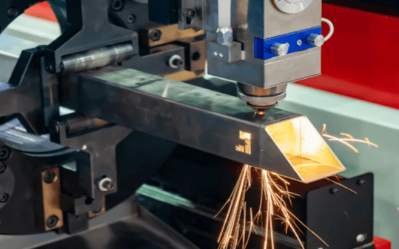
Aluminum tube cutting requires explicit confirmation of back reflection protection capability before source selection. Aluminum requires high-power fiber lasers at 6 kW and above, back-reflection protection, slower cutting speeds, and wider tolerances of ±0.3 mm compared to carbon and stainless steel.
The back reflection risk with aluminum tube is compounded compared to flat sheet aluminum cutting. On a flat sheet, back-reflected energy travels in a defined direction back toward the source. On the inner surface of an aluminum tube, secondary reflections from the curved inner wall can redirect back-reflected energy in multiple directions — some of which re-enter the delivery fiber at angles that standard threshold-protection systems may not anticipate. A source specified for aluminum tube cutting should have integrated optical isolation or active back-reflection protection, not passive threshold protection only.
The higher power requirement for aluminum tube (6 kW+) relative to carbon steel tube of the same wall thickness reflects aluminum’s lower laser energy absorption rate and higher thermal conductivity, both of which require more power input to maintain a stable cutting front.
Copper and brass tube: special process setup and source ratings
Copper and brass tube cutting demands specialized setups, tighter practical thickness limits, and higher cost than standard metals. The near-infrared absorption of copper and brass at room temperature is extremely low — typically below 5% — meaning that most of the incident laser energy reflects back toward the source during the initial piercing phase before a stable keyhole is established.
The source requirements for copper and brass tube cutting are: rated back reflection tolerance significantly above the source’s continuous output power (a 3 kW source cutting copper should be rated for back reflection events at least at 1–1.5 kW), precise low-power piercing control to establish the keyhole before applying full cutting power, and fast power ramp-up capability to transition cleanly from keyhole establishment to stable cutting without causing the keyhole to collapse.
Not all tube laser sources are rated for copper and brass cutting. Confirm the manufacturer’s explicit specification for these materials before use — the warranty and protection systems of a source not rated for copper and brass will typically not cover damage resulting from back reflection events during these materials’ cutting.
The sheet-tube combo machine: what it means for source selection
A 2-in-1 cutting system enables both sheet and pipe cutting in a single machine, ideal for small-scale production and businesses looking to avoid investing in two separate machines. These combination machines are commercially significant — a large proportion of mid-range laser cutting machine sales in the 3–6 kW range are combination sheet-tube platforms.
The source selection tension in a combination machine is real: flat sheet cutting favors higher power for thickness capability and speed, while tube cutting favors dynamic modulation capability, precise low-power piercing control, and strong back reflection protection. A source optimized entirely for sheet cutting throughput may have slow dynamic response that limits tube cutting quality; a source optimized entirely for tube cutting precision may be underpowered for the sheet cutting applications the same machine needs to handle.
The practical resolution for most combination machine buyers in the 3–6 kW range is a quasi-single-mode source (M² = 1.3–2.0) at 4–6 kW, with explicitly specified dynamic modulation bandwidth and back reflection protection. This configuration covers flat sheet up to approximately 12–16 mm on carbon steel, handles the full range of standard tube wall thicknesses, and provides the beam quality needed for stainless tube with nitrogen assist — without requiring separate source configurations for the two operating modes.
For machine builders designing combination machines, the source’s control interface matters as much as its optical specifications: the CNC controller must be able to switch the source between sheet-optimized and tube-optimized parameter sets without interrupting the workflow. Confirm that the source supports multiple stored parameter profiles accessible via its control interface, and that the switching time between profiles is fast enough for the machine’s workflow requirements. Reviewing fiber laser source options that explicitly support both operating modes before finalizing a combination machine design will prevent the common outcome of a machine that performs well in one mode but poorly in the other.
Source specifications checklist for tube and pipe cutting applications
Use this checklist when evaluating a fiber laser source for tube cutting integration. Standard sheet-cutting datasheets often omit several of these items — request them explicitly.
Power and beam quality:
- [ ] Output power matched to maximum wall thickness and material type (see table above)
- [ ] M² value at rated power — more important for stainless and aluminum tube than carbon steel
- [ ] Low-power accuracy: what is the minimum controllable power level and its accuracy? Critical for piercing control
Dynamic performance:
- [ ] Rise time from low power to full rated power
- [ ] Fall time from rated power to minimum power
- [ ] Modulation bandwidth: maximum frequency of power cycling
- [ ] Parameter switching time between stored cutting profiles
Back reflection protection:
- [ ] Protection type: passive threshold, active monitoring, or integrated optical isolation?
- [ ] Rated back reflection tolerance as a percentage or absolute power level
- [ ] Explicit material ratings: does the manufacturer confirm the source for aluminum, copper, and brass tube cutting?
Piercing capability:
- [ ] Minimum stable piercing power level
- [ ] Breakthrough detection integration: does the source interface support breakthrough-triggered power transitions?
- [ ] Piercing parameter storage: can multiple piercing profiles be stored for different wall thicknesses?
Control interface:
- [ ] Protocol compatibility with your CNC controller (analog, RS-232, EtherCAT, Modbus)
- [ ] Number of storable parameter sets
- [ ] Response time to parameter switch commands
For open-profile applications specifically:
- [ ] Dynamic back reflection monitoring confirmed (not static threshold only)
- [ ] Power cycling capability during air-crossing phases of open profile rotation
FAQ
Can I use the same fiber laser source for both tube cutting and flat sheet cutting? Yes, in a combination machine — the same source handles both applications. The requirement is that the source’s specifications cover both operating modes: adequate power for the thickest sheet you need to cut, sufficient dynamic modulation capability for the tube cutting program density you expect, and back reflection protection appropriate for the most reflective material in either application. A 4–6 kW quasi-single-mode source with explicitly specified dynamic modulation bandwidth covers both modes for most general fabrication applications. The key is confirming that the source supports stored parameter profiles for each mode and can switch between them reliably.
What power level do I need to cut 6 mm wall thickness stainless steel tube? For stainless steel tube at 6 mm wall with nitrogen assist — the standard for weld-ready edges — plan for 4 kW as a minimum and 6 kW for comfortable margin at production cutting speeds. Nitrogen-assist cutting of stainless requires approximately 30–40% more power than oxygen-assist carbon steel cutting of the same wall thickness, because the process depends entirely on the laser’s power rather than the exothermic contribution of oxidation. At 4 kW you can cut 6 mm stainless tube, but cutting speed will be limited. At 6 kW you gain speed margin and process stability on the same material.
Why does my laser source sometimes damage the back wall of small-diameter tubes during piercing? This is a piercing power control problem, not a steady-state cutting problem. The source is delivering more energy than necessary to pierce the near wall, and the excess energy continues through to the far wall before the breakthrough detection system terminates the piercing phase. Solutions in order of preference: reduce initial piercing power to the minimum that reliably pierces the wall thickness, ensure the source’s breakthrough detection integration is active and its response time is fast enough for your tube diameter and wall thickness combination, and program a deliberate power-down step immediately after piercing before transitioning to cutting power. If the source’s minimum controllable power level is too high relative to the wall thickness, a source with better low-power accuracy is the correct long-term fix.
Do open profiles like angle iron and channel steel require a different source configuration than round or square tube? They require different protection system behavior rather than a different source model. The critical requirement is that the source’s back reflection protection operates in dynamic monitoring mode rather than static threshold mode — static protection optimized for continuous metal-surface cutting may not respond correctly to the periodic air-crossing phases of open profile rotation. Confirm this capability with your source supplier before committing to open-profile applications. Power requirements for open profiles are determined by the thickest cross-section in the profile (typically the flange or web thickness), which for structural grades can reach 10–15 mm and push source power requirements above the standard 2–4 kW tube cutting range.