
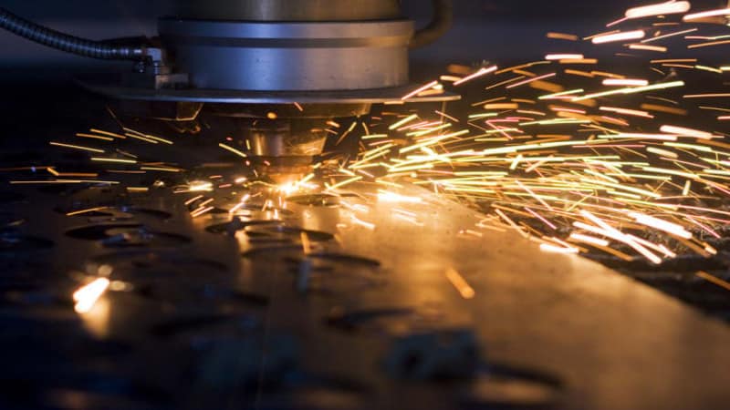
Titanium cutting with a fiber laser is achievable, precise, and increasingly common in aerospace, medical, and industrial applications. It is also categorically different from cutting any other metal in the way it fails. The failure mode is not reflectivity, not thermal conductivity, and not dross formation in the conventional sense. It is a chemical reaction — titanium’s active absorption of oxygen, nitrogen, and hydrogen at elevated temperatures — that produces a hard, brittle surface layer that can cause structural failure under load. Every process requirement in titanium cutting is a response to this chemistry, and understanding the chemistry makes every requirement logical rather than arbitrary.
Why titanium is not just another difficult metal
Most metals present laser cutting with a primarily physical challenge: high reflectivity, high thermal conductivity, or high melting point. Titanium presents a chemical challenge that sits on top of those physical properties and is more consequential than any of them.
When a fiber laser cutting machine hits titanium, the temperature exceeds 1,600°C. At temperatures above 450°C, titanium has a fatal attraction to oxygen, nitrogen, and hydrogen from the surrounding atmosphere. This absorption is not slow or partial — titanium at laser cutting temperatures will scavenge these gases from whatever atmosphere is present at the cut zone within milliseconds. The result is alpha case: a hard, brittle, interstitially hardened surface layer that forms on every surface exposed to reactive gases at elevated temperature during cutting.
In laser cutting of titanium alloys, the auxiliary gas has a significant impact on cutting quality. Oxygen-assisted cutting generates hard and brittle oxides on the cutting surface and can trigger an uncontrollable burning phenomenon. This is not a metaphor — titanium fires are documented industrial accidents, not theoretical risks. The entire process architecture for titanium cutting is built around one objective: preventing the metal from contacting reactive gases while it is above 450°C.
Alpha case — the failure mode that defines every process decision
What alpha case actually is and how it forms
Alpha case is a layer of oxygen- and nitrogen-stabilized alpha-phase titanium that forms at the surface of titanium components exposed to reactive atmospheres at elevated temperature. The interstitial oxygen and nitrogen atoms that diffuse into the titanium lattice stabilize the alpha phase and prevent the normal beta-to-alpha-to-beta phase transformations that give titanium its characteristic toughness and ductility.
The result is a surface layer with dramatically different mechanical properties from the base material: hardness two to three times higher than the bulk, near-zero elongation, and high susceptibility to crack initiation under cyclic loading. Due to the rapid temperature change during laser cutting, the titanium alloy microstructure will undergo a non-diffusive martensitic phase transformation in the heat-affected zone, creating a modified microstructure adjacent to the cut edge. On top of this transformation, if gas protection is inadequate, alpha case forms as an additional degradation layer.
The thickness of alpha case that forms during laser cutting depends on the duration and temperature of the reactive atmosphere exposure — which depends on the cutting speed, the gas protection quality, and the degree to which the cut zone is shielded from atmospheric air. A fast cut with pure argon and a properly sealed gas delivery system produces minimal or no alpha case. A slow cut with contaminated nitrogen at reduced pressure produces substantial alpha case that may extend tens to hundreds of microns into the material surface.
How to detect alpha case — color is the first indicator
The cut edge color provides immediate, visible feedback on the quality of gas protection during cutting. The color of the cut edge indicates the degree of contamination: silver or bright metallic indicates perfect shielding with no contamination and is acceptable for all applications; light straw or golden indicates minor oxygen ingress, acceptable for non-critical components; blue or dark gray indicates significant contamination and is a reject for fatigue-loaded or safety-critical parts.
This color sequence is the same thin-film optical interference effect that produces the familiar heat tint colors on welded stainless steel, but the metallurgical consequence for titanium is far more severe. A blue or gray titanium cut edge is not a cosmetic defect — it is a material failure indicator, signaling that the surface layer has been chemically altered to the point where its mechanical performance under dynamic loading is compromised.
Color inspection is a first-pass screen, not a definitive test. For aerospace and medical applications, color inspection is followed by fluorescent penetrant inspection (FPI) or X-ray testing to detect any surface or sub-surface cracking, and by chemical analysis of the edge composition if the contract requires it. The absence of discoloration is necessary but not sufficient for critical applications — it must be supplemented by the documented process records that confirm the gas purity and delivery system integrity at the time of cutting.
What applications require zero alpha case tolerance
Three application categories impose zero alpha case tolerance:
Aerospace structural components subject to vibration and fatigue loading — airframe brackets, engine components, landing gear parts — where alpha case at a cut edge creates a crack initiation site that can propagate under the cyclic stresses of flight. A part with alpha case will crack under vibration. In aerospace, that is catastrophic.
Medical implants in direct tissue contact — bone plates, dental implants, joint replacement components — where alpha case disrupts the surface chemistry that enables osseointegration, and where any microcracking at the surface creates sites for crevice corrosion in physiological fluids. For medical implants with thin and filigree structures, argon is necessary to prevent nitrogen enrichment and the formation of microcracks in the cutting area.
Chemical processing equipment in aggressive environments — where the corrosion resistance of titanium depends on the integrity of its passive film, and alpha case disrupts this film, creating local galvanic cells that accelerate corrosion at the cut edge.
For all three categories, the standard process requires argon assist gas at 99.999% purity, a fully sealed gas delivery system, and post-cutting chemical milling or mechanical finishing to remove any residual surface layer regardless of whether visible alpha case was detected.
Assist gas selection — the most consequential decision in titanium cutting
Why oxygen is completely forbidden — not just inadvisable
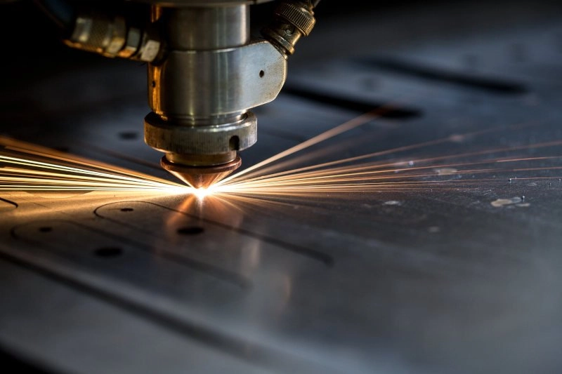
Oxygen-assisted cutting is the standard for carbon steel and a useful option for several other metals. For titanium, it is not a trade-off to evaluate — it is prohibited without exception. Oxygen reacts with titanium to form titanium oxide, which is hard and brittle. More critically, titanium has a tendency toward exothermic oxidation reactions at laser cutting temperatures that can become self-sustaining and uncontrollable — a condition colloquially described as titanium burning. Titanium fires fed by an oxygen assist gas supply are documented industrial incidents. No application justifies the use of oxygen as an assist gas for titanium cutting.
Compressed air is similarly prohibited. Air is approximately 21% oxygen and 78% nitrogen — it delivers both the reactive gas that causes burning (oxygen) and the reactive gas that causes embrittlement (nitrogen) simultaneously, at no protection whatsoever.
Nitrogen — cost-effective but chemically active for titanium
Nitrogen is not a true inert gas. At the temperatures generated during titanium laser cutting, nitrogen reacts with molten titanium to form a thin layer of titanium nitride (TiN) on the cut edge. This edge is very hard — too hard to tap threads into without breaking the tap, and too hard to weld without first grinding the TiN layer back to expose clean base material.
The practical consequence is that nitrogen-cut titanium edges require post-processing before welding or threaded fastener application, and may not be acceptable for applications where the cut edge’s ductility must match the bulk material. Nitrogen produces a clean, silvery edge that may have a slight golden hue from the TiN formation — the edge will likely need to be pickled (acid dipped) or mechanically ground to remove the recast layer before welding.
For non-critical industrial titanium components — chemical plant brackets, architectural panels, equipment enclosures — nitrogen is an acceptable and significantly more cost-effective choice than argon. Always verify the specific contract drawing or specification before selecting nitrogen; many aerospace and medical drawings explicitly specify argon as the required shielding gas.
Argon — the only truly inert option and when it’s required
Argon is a noble gas that does not react with titanium at any temperature achievable in laser cutting. An argon-shielded titanium cut produces a chemically pure edge that retains the ductility of the base metal, without the titanium nitride hardening that nitrogen produces. This makes argon the only acceptable gas for aerospace, medical, and other critical titanium applications.
The cost premium for argon over nitrogen is real and significant — plan for argon to add meaningfully to the consumable cost per part, and factor this into pricing for argon-specified work. The gas delivery system requirements are also more stringent: to use argon effectively, the gas delivery system must be 100% leak-proof. Even a 0.1% leak of atmospheric air into the gas line can contaminate the cut and cause the part to fail an X-ray or dye-penetrant inspection test. A system that is adequately sealed for stainless steel nitrogen cutting may not meet this standard for aerospace titanium argon cutting — verify and test the delivery system before first production use.
Gas purity for titanium cutting must be 99.999% (five nines) — one order of magnitude above the 99.99% standard for stainless steel nitrogen cutting. Request purity certificates from the gas supplier for each cylinder lot, and maintain those certificates in the job traveler documentation for traceability.
Helium and helium-argon mixtures — for thick titanium
For titanium plates above 10 mm, some shops use helium or a helium-argon mixture. Helium’s significantly higher thermal conductivity removes heat from the cut zone faster than argon, reducing the time the material spends above the critical 450°C threshold and directly reducing alpha case formation. Helium is also more inert than argon in the sense that its higher thermal conductivity reduces peak temperatures at the cut zone, further limiting the kinetics of interstitial gas absorption.
The cost constraint is severe: helium is significantly more expensive than argon, which is already more expensive than nitrogen. In practice, helium and helium-argon mixes are used only in specialized military or defense contracts where the performance requirement justifies the cost and where the end customer is absorbing the gas cost premium. For commercial aerospace and medical work, pure high-pressure argon at sufficient pressure remains the standard.
Gas purity and delivery system — the requirements most setups fail to meet
The gas purity and delivery system requirements for titanium cutting are more stringent than for any other metal, and they are the most common area where otherwise adequate setups produce unacceptable results.
99.999% purity is the minimum acceptable specification for any inert gas used in titanium cutting — whether nitrogen for non-critical work or argon for critical applications. This is one full purity grade above the 99.99% standard used for stainless steel nitrogen cutting. The difference matters because titanium’s affinity for interstitial gases is high enough that trace contamination at the 0.001% level is sufficient to produce visible edge discoloration, and at the 0.01% level is sufficient to produce measurable alpha case.
The delivery system — regulators, hoses, fittings, and connections from the gas cylinder to the nozzle — must be leak-tested before first titanium production use, after any maintenance that involves disconnecting and reconnecting fittings, and at regular intervals thereafter. Even a 0.1% atmospheric air ingress through a micro-leak in the gas delivery path is sufficient to cause the part to fail fluorescent penetrant or X-ray inspection. Leak testing can be performed with a helium leak detector or by flowing argon through the system while monitoring an oxygen analyzer at the nozzle exit — the measured oxygen content at the nozzle should be below 10 ppm for aerospace applications.
Power requirements — titanium vs. other metals at equivalent thickness
The 1.5–3× power premium over mild steel
Cutting lightweight metals including titanium requires 1.5–3× the laser power of mild steel for the same thickness. This is a larger premium than aluminum (30–40% over carbon steel) and reflects titanium’s combination of properties: while its thermal conductivity (~22 W/m·K for Grade 2) is low enough to concentrate heat at the cut zone, its melting point (~1,668°C for Grade 2, slightly higher for Ti-6Al-4V) is higher than carbon steel’s, and the inert gas cutting process provides no exothermic chemical energy supplement the way oxygen-assisted steel cutting does.
The inert gas cutting requirement is the dominant factor in the power premium. Nitrogen-assisted stainless steel cutting requires 30–40% more power than oxygen-assisted carbon steel cutting for the same reason — no chemical energy contribution. Titanium’s higher melting point amplifies this requirement further.
Practical power thresholds by thickness
| Titanium thickness | Recommended power | Cutting speed | Recommended gas | Gas pressure | Notes |
|---|---|---|---|---|---|
| 0.1–0.5 mm | 100–500 W (pulsed/MOPA preferred) | 1–5 mm/s | Argon 99.999% | 6–10 bar | Medical/thin foil; pulsed operation minimizes HAZ |
| 0.5–2 mm | 500–1,500 W | 1–4 m/min | Argon or N₂ 99.999% | 10–14 bar | Application determines gas choice |
| 2–5 mm | 2,000–4,000 W | 0.5–2 m/min | Argon or N₂ 99.999% | 14–18 bar | Argon for aerospace/medical; N₂ for industrial |
| 5–10 mm | 4,000–6,000 W | 0.3–1 m/min | Argon 99.999% | 16–20 bar | Slow speed critical for gas shielding effectiveness |
| 10–15 mm | 6,000–10,000 W | 0.2–0.6 m/min | Argon or Ar/He mix | 18–25 bar | Alpha case risk increases with thickness |
| Above 15 mm | 10,000 W+ or waterjet | 0.1–0.3 m/min | N/A — consider waterjet | — | >12mm: laser heat input becomes too high for economical alpha case removal |
A 6 kW fiber laser can typically cut titanium up to 20 mm, while higher-power 12 kW+ systems can process even thicker plates — but the economic and quality case for laser over waterjet diminishes sharply above 12–15 mm for aerospace-grade work, because the alpha case layer generated by laser at heavy thickness requires extensive removal that waterjet avoids entirely.
Focus position — why titanium needs deeper negative focus
Titanium cutting uses a more deeply negative focus position than other metals. For plates under 10 mm, set the focal point 2–4 mm below the material surface. For plates above 10 mm, set it 3–6 mm below. These values are deeper than the typical negative focus used for stainless steel (−2 to −4 mm) and significantly deeper than carbon steel.
The physical reason is specific to titanium’s cutting dynamics. Even with good inert gas shielding, the titanium oxide that forms at the very start of the piercing phase — before the inert atmosphere is fully established — creates a surface layer that resists melt ejection. The cut must maintain sufficient energy density at the exit face of the material to push the melt through this resistant layer. A deep negative focus ensures that the beam, which is converging toward the focal point, maintains high intensity through the full material depth and particularly at the bottom of the kerf where the cut must complete.
The deeper focus also produces a slightly wider kerf profile that allows the inert gas jet to penetrate further into the cut channel, improving shielding at depth — which is precisely where the material spends the most time above the critical temperature and is most vulnerable to alpha case formation.
The piercing problem — why titanium piercing fails differently from other metals
Piercing is the highest-risk phase of any titanium cut, and the failure mode is unlike copper, aluminum, or stainless steel. The combination of a cold surface, high reflectivity, and titanium’s instantaneous reactivity with any atmospheric gases present at the pierce point creates a cascade of problems that full-power instant piercing cannot manage.
Do not use a full-power instant pierce on titanium. Start at 30–40% of cutting power, hold for 200–400 milliseconds, then ramp up to cutting power. This graduated approach serves three simultaneous purposes: it allows the surface to heat gradually, reducing the initial reflectivity spike that would cause back reflection damage to the source; it gives the inert gas time to establish a stable protective flow at the pierce point before the full beam arrives; and it reduces the probability of molten titanium spatter coating the nozzle, which degrades the gas shielding quality for all subsequent cuts.
If the machine supports pulsed pierce, use a frequency around 5–10 kHz with a duty cycle of 40–50%. The pulsed pierce mode is particularly effective for titanium because the off-time between pulses allows both heat dissipation and gas flow establishment before the next pulse delivers energy.
For production setups cutting titanium at volume, developing and locking specific pierce parameters — not simply using the cut parameters with a pierce time appended — is essential. The pierce parameters for titanium will look very different from the cut parameters, and the transition between them must be smooth and controlled. Machines that can store separate pierce and cut parameter sets and transition between them programmatically are better suited to titanium production than those requiring manual parameter management.
Grade 2 vs. Ti-6Al-4V — why the alloy matters for process setup
Grade 2 (commercially pure titanium) — the baseline
Grade 2 titanium is commercially pure titanium with minimum 99.2% titanium content. It offers excellent corrosion resistance, good formability, and relatively straightforward laser cutting behavior compared to titanium alloys. Its melting point is approximately 1,668°C, its thermal conductivity is approximately 22 W/m·K, and its melt viscosity is moderate.
For ultra-thin Grade 2 titanium sheets (0.15 mm), research using a 200 W modulated fiber laser achieved a minimum kerf width of 23.4 µm at 90 W power and 2 mm/s cutting speed, with argon as the shielding gas. This demonstrates the precision achievable with appropriate laser source and gas selection on Grade 2, and the figure — 23.4 µm kerf on 0.15 mm sheet — is directly relevant to medical device manufacturers producing thin-walled implant structures.
Grade 2 is used primarily in chemical processing equipment, architectural applications, medical device housings, and marine hardware. These applications cover a range of quality requirements from industrial (nitrogen acceptable) to critical (argon required), depending on the specific end use.
Ti-6Al-4V (Grade 5) — the aerospace alloy with different cutting behavior
Ti-6Al-4V is the most widely used titanium alloy globally, accounting for approximately 50% of all titanium production. The 6% aluminum and 4% vanadium additions produce a dual-phase (alpha-beta) alloy with significantly higher strength than Grade 2 — approximately twice the yield strength — but also different and more demanding laser cutting behavior.
The dual-phase microstructure of Ti-6Al-4V undergoes a non-diffusive martensitic phase transformation in the heat-affected zone during laser cutting, producing a transformed microstructure that differs from both the alpha and beta phases present in the base material. This transformation is a fixed consequence of the thermal cycle and cannot be avoided — but it can be minimized in extent by minimizing the heat-affected zone, which is achieved through higher cutting speeds (minimizing dwell time per point) and optimal gas shielding (minimizing the thermal contribution of exothermic surface reactions).
The practical process differences from Grade 2: Ti-6Al-4V requires approximately 15–20% lower cutting speed than Grade 2 at the same thickness and power, reflecting the higher strength that must be overcome in the melt. The melt viscosity is higher, requiring somewhat higher gas pressure to ensure complete melt ejection from the kerf. And the alpha case sensitivity is greater — the transformed HAZ microstructure that forms at the cut edge of Ti-6Al-4V is more sensitive to interstitial contamination than Grade 2, making the gas purity and delivery system requirements even more critical.
Do not use Grade 2 parameters for Ti-6Al-4V production without independent validation. Develop separate parameter sets for each alloy, and treat them as distinct materials even when the nominal thickness and power are the same.
Safety — the risks that make titanium cutting categorically different
Titanium cutting has a safety profile that is unlike any other metal processed on industrial fiber laser machines, and it is the one dimension of titanium cutting most inadequately covered in process guides.
Titanium dust and fines generated during cutting are combustible — and a dust collector that is not specifically designed and maintained for titanium can become a fire and explosion source. Titanium swarf is classified as a flammable solid when particle size is sufficiently small, and the fine particles generated by laser cutting — which are much smaller than machining chips — can accumulate in dust collection equipment and ignite from electrostatic discharge or a hot particle.
Three operational requirements follow from this risk:
Dedicated dust collection. A dust collector used for titanium cutting should not be shared with cutting of other metals. Mixing titanium fines with steel or aluminum fines changes the combustion chemistry and may increase ignition risk. Use a dedicated collection system with explosion-rated components for titanium cutting work.
Regular cleaning intervals. Do not allow titanium fines to accumulate in the dust collector, ductwork, or on horizontal surfaces near the cutting table. Establish a cleaning interval — daily for high-volume titanium cutting, weekly for occasional titanium work — and enforce it. The fire risk scales directly with accumulated fines.
Dry storage and disposal. Titanium fines should be stored dry and away from other combustible materials before disposal. Wet methods of fines control — used in some waterjet and grinding operations — are not applicable to fiber laser titanium cutting exhaust.
These requirements are not suggestions. Facilities that cut titanium regularly must review their local fire code requirements and their machine manufacturer’s safety documentation for titanium-specific guidance. The regulatory requirements vary by jurisdiction, but the underlying physics are universal.
Application-specific requirements — aerospace, medical, and industrial
Aerospace structural components
Aerospace titanium cutting operates under the most demanding quality and traceability requirements of any laser cutting application. Gas purity certificates showing 99.999% argon or nitrogen must be part of the job documentation. Machine calibration records must be current. Every cut part must be traceable to the specific heat number of the raw material billet. The CNC controller records the exact power, speed, and gas pressure used for every job — this digital thread of traceability is what auditors require.
Post-cutting inspection for aerospace titanium typically includes visual inspection (color check), fluorescent penetrant inspection (FPI) to detect surface and near-surface cracks, and dimensional verification. Many aerospace drawings specify a minimum material removal requirement after laser cutting — typically 0.1–0.5 mm of material removed from cut surfaces by grinding, electrochemical machining, or chemical milling — to eliminate any residual alpha case regardless of whether it was detected visually.
Medical implants and devices
Medical titanium cutting prioritizes two outcomes: minimum kerf width (relevant for thin filigree structures in implants) and chemically clean edge chemistry (argon required, as nitrogen produces TiN that disrupts osseointegration). Research demonstrates that a minimum kerf width of 23.4 µm is achievable on 0.15 mm Grade 2 titanium with a modulated fiber laser and argon shielding — a specification relevant to the cut quality required for stent structures, bone fixation plates, and surgical instrument components.
For fiber laser sources used in medical titanium production, the beam quality specification is particularly important: a lower M² produces a smaller focal spot, which is the direct determinant of minimum achievable kerf width. Sources specified for general industrial cutting may not achieve the beam quality needed for the finest medical device features.
Industrial applications (chemical processing, architecture)
Industrial titanium applications — chemical plant equipment, heat exchangers, architectural cladding panels — have substantially less stringent quality requirements than aerospace or medical. Nitrogen is typically acceptable as the assist gas, eliminating the significant cost premium of argon. Edge color inspection is performed but with less stringent rejection criteria — light straw discoloration that would be rejected for aerospace may be acceptable for a chemical plant bracket.
Post-cutting finishing requirements are application-specific: chemical plant equipment may require edge passivation treatment to restore the passive titanium oxide film; architectural panels typically require only deburring and cleaning; structural brackets may require no edge treatment beyond visual inspection.
Source selection checklist for titanium cutting
Power and beam quality:
- Source power meets the 1.5–3× carbon steel equivalent requirement for the target titanium thickness and grade
- For medical device applications: M² specified at rated power, ≤ 1.3 preferred for minimum kerf width capability
- For thin titanium (below 1 mm): confirm MOPA or pulsed capability for HAZ-controlled processing
Gas infrastructure:
- Gas supply specified at 99.999% purity minimum — one grade above stainless steel nitrogen standard
- Gas delivery system leak-tested to < 10 ppm oxygen at nozzle exit for aerospace applications
- Purity certificates available for all gas lots and maintainable in job traveler documentation
- Separate gas regulators and lines confirmed for titanium — not shared with reactive gas (O₂) systems
Process parameter capability:
- Graduated pierce capability confirmed — separate pierce parameters from cut parameters, 30–40% power ramp
- Pulsed pierce mode available (5–10 kHz, 40–50% duty cycle) for thin and medium titanium
- Negative focus position range covers −2 to −6 mm for the target thickness range
Safety infrastructure:
- Dedicated titanium dust collection system — not shared with other metals
- Dust collection equipment rated for flammable fines
- Cleaning interval established and documented for titanium fines removal
Traceability (aerospace and medical):
- CNC parameter logging active — power, speed, gas pressure recorded per job
- Gas lot purity certificates retained with job traveler
- Material heat number traceability maintained from billet to finished part