
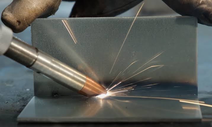
Galvanized steel is one of the most widely processed materials in laser cutting shops — HVAC ductwork, automotive body panels, agricultural equipment, construction components. It is also the material most likely to cause mid-cut failures, unexplained dross formation, and rapid protective window degradation that experienced operators attribute to “something being off” without being able to identify the specific mechanism. The zinc coating is that mechanism. Understanding how zinc behaves under a fiber laser beam explains every challenge in galvanized steel cutting and points directly to the solutions.
Why galvanized steel is not just “carbon steel with a coating”
The instinct to treat galvanized steel as carbon steel with a slightly modified parameter set is understandable but incorrect. The zinc coating is not a passive surface layer that gets burned away as part of the cutting process. It is an active participant in the cutting physics — one that intervenes before the steel base even begins to melt.
The steel base metal melts at approximately 1,370°C. The zinc coating vaporizes at a much lower 907°C. When a fiber laser beam hits the surface of galvanized steel, the zinc coating does not melt gradually and flow away. It boils explosively into vapor before the steel beneath it has reached its melting point. This phase transition — zinc from solid to vapor while the steel is still solid — drives every challenge in galvanized steel cutting: the melt pool disruption, the dross formation, the optical contamination, and the mid-cut failures.
The good news is that the steel base itself cuts essentially the same way as uncoated carbon steel. The challenge is entirely about managing the zinc coating’s behavior during that cutting process. Every solution in this guide is an intervention in the zinc vaporization sequence, not in the steel cutting physics.
The zinc vaporization sequence — what actually happens when the beam hits galvanized steel
Phase 1: zinc explodes before steel melts
The event sequence when a fiber laser beam contacts galvanized steel is straightforward but consequences are far-reaching. The beam heats the surface rapidly. Before the steel substrate reaches 1,370°C, the zinc coating reaches its boiling point of 907°C and transforms from solid to vapor nearly instantaneously. This phenomenon creates a high-velocity jet of zinc oxide (ZnO) gas that mixes with the assist gas and creates a massive plume of fine white particulate — this is not just smoke, it is a cloud of metal nanoparticles.
The speed and pressure of this zinc vapor jet is significant. It is not a slow outgassing — it is a pressure event that injects high-velocity material into the cutting zone at the moment the beam is trying to establish stable contact with the steel substrate. Everything that follows — melt pool disruption, dross formation, optical contamination — begins with this initial explosion.
Phase 2: zinc vapor disrupts the melt pool
Once the zinc has vaporized and the steel begins to melt, the cutting process enters its second challenge phase. The high-pressure zinc vapor disrupts the molten steel pool — it prevents the assist gas from cleanly ejecting the liquid steel from the kerf, leading to slag and dross formation. The zinc vapor is not inert — it is a pressurized gas jet originating from within the cut zone itself, injecting energy and mass into the melt pool at the same time the assist gas is trying to push that melt downward and out of the kerf.
The result is dross formation that is more severe and more inconsistent than on equivalent bare carbon steel. The molten steel that should be ejected cleanly by the assist gas is instead disturbed by the internal zinc vapor pressure, producing irregular ejection patterns and dross adhesion on the lower cut edge. This is why parameter sets that produce clean bottom edges on bare carbon steel routinely produce dross on galvanized steel — not because the steel cutting parameters are wrong, but because the zinc vapor is adding an uncontrolled variable to the melt ejection dynamics.
Phase 3: zinc oxide cloud blocks the beam — the mid-cut failure mechanism
The most disruptive failure mode specific to galvanized steel is the mid-cut interruption — the cut is progressing normally and then suddenly fails, leaving a black spot on the sheet and an incomplete cut. This failure is not random. It has a specific physical cause that can be reproduced and prevented once understood.
Galvanized steel sheets have variation in zinc coating thickness across the sheet surface — some areas are coated more heavily than others as a result of the hot-dip galvanizing process. When the laser hits a thick pocket of zinc, it vaporizes instantly, creating a plasma cloud that blocks the laser beam. This ZnO plasma cloud has enough optical density to absorb and scatter the laser beam before it reaches the steel substrate. The beam loses contact with the material, the cut interrupts, and the plasma cloud leaves a carbonized mark on the sheet surface.
This failure mode cannot be eliminated entirely by parameter adjustment alone, because the coating thickness variation is a material property, not a process variable. It can be managed through two primary interventions: increasing assist gas pressure to physically disperse the plasma cloud faster before it has time to build up to beam-blocking density, and using high cutting speed to reduce the dwell time at any given point — limiting the time during which a localized thick coating can build a plasma cloud large enough to interrupt the cut.
How zinc coating thickness affects cutting difficulty — the specification nobody talks about
Galvanized steel is commercially specified by its zinc coating weight, which directly determines coating thickness. The designation system varies by standard (ASTM A653 in North America, EN 10346 in Europe), but the underlying physics is the same: more zinc per unit area means more zinc to vaporize per unit of cutting path.
Common designations and their approximate coating thicknesses:
| Coating designation | Approximate coating weight | Approximate thickness per side | Relative cutting difficulty | Optical contamination risk |
|---|---|---|---|---|
| G30 / Z90 | 90 g/m² total | ~6.5 µm per side | Baseline | Moderate |
| G60 / Z180 | 180 g/m² total | ~13 µm per side | Moderate — 2× zinc vs G30 | High |
| G90 / Z275 | 275 g/m² total | ~20 µm per side | High — 3× zinc vs G30 | Very high |
| G115 / Z350 | 350 g/m² total | ~25 µm per side | High | Very high |
| G235 / Z600 | 600 g/m² total | ~43 µm per side | Maximum — 6.5× zinc vs G30 | Severe |
The practical implication is direct: G235 material produces approximately 6.5× the zinc vapor volume per unit of cutting length compared to G30. This means 6.5× the melt pool disruption, 6.5× the optical contamination rate, and a significantly higher frequency of mid-cut failures from zinc plasma cloud events. A parameter set developed on G60 material will not produce the same results on G235 material, even at the same steel thickness. Specifying the exact coating designation of the material being processed — and developing parameters for each coating weight, not just for each steel thickness — is the process discipline that separates consistent galvanized steel cutting from unpredictable results.
The counterintuitive speed strategy — why cutting fast is the solution, not the problem
There is a persistent contradiction in the advice given about galvanized steel cutting speed. Some sources recommend slowing down to “give the laser more time to cut through the coating.” This advice is physically incorrect and produces worse results. The correct strategy is the opposite.
Use high power and high speed — get in and get out before the zinc knows what hit it. If you move slowly, the heat spreads, boiling the zinc coating inches away from the cut. The physics behind this recommendation is specific and important.
Zinc’s boiling point (907°C) is reached at temperatures that exist not only directly under the laser beam, but also in a heat-affected zone extending some distance around the beam. At slow cutting speeds, the laser dwells at each point long enough for significant heat to conduct laterally into the surrounding material — the heat-affected zone expands, the 907°C isotherm extends further from the kerf centerline, and zinc coating across a wide band on either side of the cut vaporizes. This wide-area zinc vaporization produces more total zinc vapor, a larger melt pool disruption, and a wider contamination plume that loads the cutting head optics faster.
At high cutting speed, the laser moves through each point quickly enough that the heat-affected zone remains narrow. The 907°C isotherm stays close to the kerf centerline. Zinc vaporization is confined to a small zone immediately adjacent to the cut path. Total zinc vapor production per unit of cutting path is reduced, melt pool disruption is less severe, and optical contamination accumulates more slowly.
The strategy is to use high-power nitrogen cutting rather than oxygen cutting where possible, and to optimize for speed to minimize zinc vaporization — not to maximize throughput, but because high speed is physically the correct process strategy for this material. This is not a trade-off between speed and quality. At correct power levels, higher speed produces better quality on galvanized steel than slower speed does.
The practical implementation is to start with a cutting speed at or near the maximum for the steel thickness — the same speed you would use for bare carbon steel at that thickness — and then verify that the power is sufficient to maintain clean cutting at that speed. Do not start with reduced speed and compensate with reduced power. Start with appropriate speed and verify power adequacy.
Assist gas selection — oxygen, nitrogen, or air, and why the choice is more complex
Why oxygen is a special case for galvanized steel
Oxygen-assisted cutting on galvanized steel behaves differently than on bare carbon steel, because oxygen reacts not only with the iron in the steel base but also with the zinc coating. The oxygen-zinc reaction produces zinc oxide (ZnO), which vaporizes at the cutting temperatures involved. This chemical interaction actually assists in clearing the zinc coating from the cut path — the exothermic zinc oxidation reaction contributes heat energy at the zinc-laser interaction zone, helping to push through the zinc coating before engaging the steel base.
Oxygen is well-suited for cutting thicker galvanized steel, as it produces a cleaner cut edge and reduces the risk of burrs. For galvanized steel above approximately 3 mm, oxygen assist can improve cut quality compared to nitrogen, particularly for the bottom-edge dross that nitrogen cutting sometimes struggles to control on heavier gauges. The trade-off is an oxidized edge that requires additional surface preparation before painting, powder coating, or welding.
For applications where the cut edge will be painted directly without secondary treatment — a common scenario in HVAC and construction applications — oxygen-assisted cutting is a practical choice that trades some edge cleanliness for better melt ejection on heavier gauges.
Nitrogen for clean edges — when and why
Nitrogen produces oxide-free cut edges on galvanized steel, which is necessary for applications requiring weld-ready or paint-adhesion-ready cut surfaces. Nitrogen does not chemically interact with the zinc coating the way oxygen does, so it relies entirely on mechanical pressure to eject the zinc vapor and molten steel from the kerf.
For thin galvanized steel, high-power nitrogen cutting at high speed produces the best combination of edge quality and fume reduction — the high speed limits zinc vaporization area, and the nitrogen provides clean ejection without introducing oxidation chemistry. Nitrogen pressure requirements for galvanized steel are higher than for equivalent bare carbon steel: the zinc vapor adds a gas load to the kerf that the nitrogen must clear in addition to the molten steel. Plan for nitrogen pressures 15–20% above what you would use for the same thickness in bare carbon steel.
Nitrogen purity should be 99.99% or higher. Oxygen contamination in the nitrogen supply introduces the chemistry you were trying to avoid by choosing nitrogen over oxygen. Water vapor contamination is particularly problematic on galvanized steel because it reacts with zinc oxide to form zinc hydroxide compounds that deposit on optical surfaces and are harder to clean than pure ZnO.
Compressed air — the cost-effective option for non-critical applications
Compressed air is viable for thin galvanized steel (below approximately 2 mm) in applications where edge oxidation is acceptable and cost efficiency is the primary concern. The trade-off is visible oxidation at the cut edge and somewhat more aggressive optical contamination compared to nitrogen, since the moisture and oil content of compressed air compounds the ZnO deposition problem.
If using compressed air, the air supply must be rigorously dried and filtered: oil contamination from the compressor reaches the protective window and bakes into the ZnO deposits, forming a hard composite contamination that is extremely difficult to remove without damaging the optical surface. Use an oil-free compressor and a desiccant dryer rated for laser cutting service, not just a standard refrigerant air dryer.
The optics contamination problem — how zinc oxide threatens your cutting head
Of all the ways galvanized steel cutting differs from carbon steel cutting, the impact on cutting head optics is the one with the most direct effect on operating cost — and the one most commonly underestimated when setting up a production plan for galvanized steel.
ZnO nanoparticles generated during galvanized steel cutting are smaller and lighter than the combustion particles from carbon steel cutting. They remain airborne longer and penetrate further into the cutting head’s optical cavity before the assist gas curtain stops them. The result is a white powder deposit on the protective window — and potentially on the focusing lens above it — that accumulates much faster than carbon steel residue does.
Optical clarity in the laser path is essential for long-term equipment reliability — ZnO contamination on the protective window reduces laser transmission, causes thermal lensing from uneven heating of the contaminated area, and if left to progress, transfers thermal damage from the contaminated window to the focusing lens. In production environments cutting significant volumes of galvanized steel, protective window replacement frequency on galvanized cutting programs is typically 3–5× higher than on equivalent carbon steel programs.
The operational response has three components:
More frequent inspection: Inspect the protective window at every production break, not just at shift start, when running galvanized steel. The contamination rate is high enough that a window that was clean at the start of a shift can be significantly degraded by mid-shift.
Higher assist gas pressure: Increasing the assist gas pressure creates a stronger gas curtain at the nozzle exit, reducing the fraction of ZnO particles that penetrate back up into the cutting head. This is one of the reasons galvanized steel cutting benefits from higher gas pressure than bare carbon steel — not just for melt ejection, but for optics protection.
External fume extraction positioned correctly: The fume extraction system should be positioned to capture the ZnO plume as it rises from the cut zone, before it has time to recirculate into the machine enclosure. An extraction system positioned correctly for carbon steel may need repositioning for galvanized steel, because ZnO particles rise faster and in a more concentrated plume than carbon steel combustion products.
Galvanized vs. galvannealed — the processing difference that matters
Galvannealed steel (sometimes designated “GA” or “ZF” in European standards) has a zinc-iron alloy coating rather than pure zinc. The galvannealing process involves heating standard galvanized steel to allow iron from the steel substrate to diffuse into the zinc coating, forming zinc-iron intermetallic compounds throughout the coating thickness.
Galvannealed steel has a zinc-iron alloy coating that is harder and less “explosive” than standard galvanized steel. It actually cuts slightly better and paints more easily. The higher iron content of the galvannealed coating raises its effective vaporization temperature compared to pure zinc, reducing the explosive character of the coating vaporization. The result is less violent zinc vapor injection into the melt pool, somewhat reduced optical contamination rate, and modestly better cut quality at equivalent parameters.
The practical guidance is: use the same parameter set for galvannealed steel as for standard galvanized steel. The galvannealed material will typically produce somewhat cleaner results with the galvanized parameters — if you have time to develop separate parameters, galvannealed can often tolerate slightly lower gas pressure with equivalent or better results, but this optimization is not required for acceptable production quality.
The main distinction between the two for production planning is post-processing: galvannealed steel is significantly easier to paint directly after laser cutting because its zinc-iron alloy surface has better paint adhesion characteristics than the smooth pure zinc surface of standard galvanized steel. If your downstream process involves direct painting without intermediate surface treatment, galvannealed is the preferable input material.
Health and safety — zinc fumes are a production issue, not just a safety poster
Zinc oxide fumes from galvanized steel cutting carry a genuine occupational health risk — metal fume fever, characterized by flu-like symptoms that typically resolve within 24–48 hours after exposure ends, is a documented occupational hazard from ZnO inhalation. This is not theoretical: operators cutting galvanized steel in inadequately ventilated environments report this illness. The health risk is real and should not be dismissed as background manufacturing noise.
The production-focused rationale for proper fume extraction goes beyond regulatory compliance. ZnO particles that are not extracted recirculate through the machine enclosure and deposit on every surface — motion system components, linear guides, ball screws, and the source’s own ventilation inlets. Accumulated ZnO on motion system components accelerates wear. ZnO particles entering the source’s electrical cabinet through ventilation openings contaminate drive boards and fan bearings. The fume extraction system is protecting the machine and the source, not just the operators.
Minimum requirements for galvanized steel fume extraction: a filtration system rated for fine metallic particulates (HEPA grade for particles down to 0.3 µm, given that ZnO nanoparticles are sub-micron), positioned to capture the ZnO plume directly rather than allowing it to recirculate through the machine enclosure. Where feasible, dedicated extraction at the cutting head level — a nozzle or hood positioned close to the cut zone — provides better capture efficiency than relying solely on enclosure-level extraction.
Power and parameter setup — a practical reference for galvanized steel
The base principle for galvanized steel parameter development is: start with the bare carbon steel parameter set for the equivalent thickness, then apply the following adjustments.
Power: Increase by approximately 10–15% above bare carbon steel parameters. The additional power accounts for the energy absorbed by zinc vaporization that would otherwise have gone into the steel base metal. The zinc vaporization is not free — it consumes a fraction of the laser energy that would otherwise contribute to cutting.
Speed: Match or exceed the bare carbon steel cutting speed. Do not reduce speed to compensate for the zinc coating. High speed is the primary process strategy, not a variable to be traded away for other adjustments.
Gas pressure: Increase by 15–20% above bare carbon steel parameters for the same assist gas. The additional pressure is needed for two functions: melt pool management (compensating for zinc vapor disruption) and optics protection (stronger gas curtain to reduce ZnO penetration into the cutting head).
| Steel thickness | Recommended power (vs. bare CS) | Cutting speed | Assist gas | Pressure | Notes |
|---|---|---|---|---|---|
| 0.5–1 mm | CS + 10% | Match or exceed CS speed | N₂ or Air | 10–14 bar | Air viable for non-critical applications |
| 1–2 mm | CS + 10–12% | Match CS speed | N₂ preferred | 12–16 bar | Window inspection every 2 hours |
| 2–3 mm | CS + 12–15% | Match CS speed | N₂ or O₂ | 14–18 bar (N₂) / 0.6–1 bar (O₂) | O₂ improves edge quality on heavier gauge |
| 3–5 mm | CS + 15% | Match CS speed | O₂ for clean cut; N₂ for clean edge | 16–20 bar (N₂) / 0.6–0.8 bar (O₂) | Frequent window inspection required |
| Above 5 mm | CS + 15% | Match CS speed | O₂ | 0.5–0.8 bar | Higher zinc volume; aggressive optics maintenance schedule |
Piercing parameters: Develop separate pierce parameters for galvanized steel. The pierce phase is where zinc vapor pressure builds up most rapidly — the beam is stationary while the zinc vaporizes, creating the maximum zinc vapor concentration before cutting begins. Reduce pierce power to 60–70% of cutting power, extend pierce dwell time proportionally to compensate, and increase gas pressure by an additional 10–20% above cutting parameters during the pierce phase. This reduces the intensity of the zinc vapor event during piercing while still establishing the keyhole needed to begin cutting.
For high coating weight materials (G90/G235): Increase gas pressure by an additional 10% above the table values, inspect the protective window every 60–90 minutes of active cutting time, and plan for protective window changes as a scheduled production activity rather than an unplanned maintenance event.
For any production environment cutting significant volumes of galvanized steel, maintaining a dedicated galvanized steel parameter set separate from your carbon steel parameters is essential — sharing parameter sets between galvanized and bare carbon steel is one of the most common sources of inconsistent results in mixed-material laser cutting shops.
FAQ
Can I use the same parameters for galvanized steel as for plain carbon steel? No — galvanized steel requires specific adjustments: approximately 10–15% more power to account for energy consumed by zinc vaporization, 15–20% higher assist gas pressure for melt pool management and optics protection, and a separate piercing parameter set. The cutting speed should match or exceed bare carbon steel — do not reduce speed as a compensation for the zinc coating. Using bare carbon steel parameters on galvanized steel produces more dross, faster optical contamination, and higher frequency of mid-cut failures than purpose-developed galvanized parameters.
Why does my cut suddenly stop mid-way through galvanized steel, leaving a black mark? This is the zinc plasma cloud failure mode. When the laser hits a thick pocket of zinc coating, it vaporizes instantly, creating a plasma cloud that blocks the laser beam. The cut interrupts because the beam cannot reach the steel substrate through the ZnO plasma. Solutions in order of effectiveness: increase assist gas pressure to disperse the plasma cloud faster; increase cutting speed to reduce the dwell time at any given point; verify that the coating weight of the material you are cutting matches what your parameters were developed for — switching from G60 to G90 material without adjusting parameters significantly increases mid-cut failure frequency.
How often should I replace the protective window when cutting galvanized steel? Substantially more often than for carbon steel — typically 3–5× the replacement frequency. In active galvanized steel production, inspect the protective window every 2 hours of cutting time rather than every shift. A window that appears visually clean may still have enough ZnO micro-deposit to cause significant thermal lensing and apparent power loss. Weigh the cost of more frequent window replacement against the cost of degraded cut quality and the risk of window damage propagating to the focusing lens — protective windows are inexpensive; focusing lenses are not.
Is galvannealed (GA) steel easier to cut than standard galvanized (GI) steel? Slightly. Galvannealed steel has a zinc-iron alloy coating that is harder and less explosive than standard galvanized — it cuts slightly better and paints more easily. The zinc-iron intermetallic coating has a higher effective vaporization temperature than pure zinc, reducing the violent character of the zinc phase transition during cutting. The practical guidance is to use the same parameters as for standard galvanized — galvannealed will typically produce somewhat cleaner results with those settings. The primary benefit of galvannealed for most production environments is in post-processing: the zinc-iron surface has better paint adhesion than pure zinc, making galvannealed the preferable choice when direct painting without intermediate surface treatment is required.