
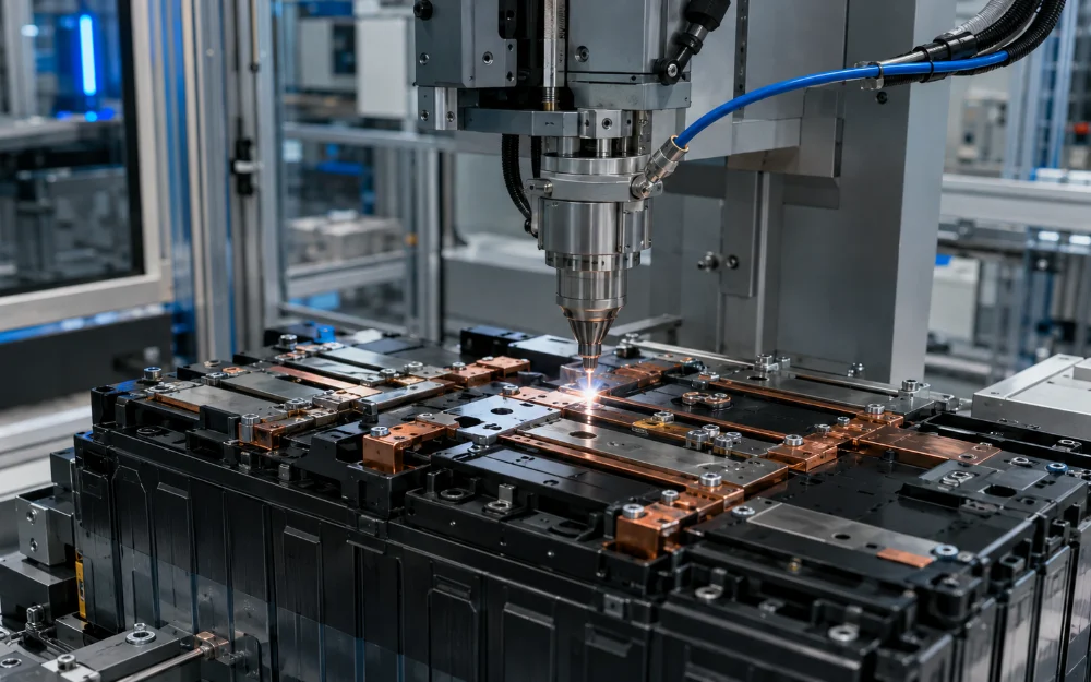
Selecting a fiber laser source for EV battery busbar welding should start with the joint—not with a target laser wattage. Busbar material, terminal material, thickness, plating, overlap, required penetration, electrical resistance, heat-input limit, and production speed determine the power, beam quality, spot characteristics, modulation, and beam-control strategy the source must support.
This matters because two fiber laser sources with the same rated output can behave very differently at the workpiece. BPP, fiber core diameter, focused spot size, beam profile, optical configuration, and temporal control determine how that power is concentrated and distributed through the joint.
OEMs developing battery welding equipment can review CW fiber laser source options for battery welding, but the final source specification should always be derived from a validated busbar-to-terminal process.
What Makes EV Battery Busbar Welding Different From General Laser Welding?
A battery busbar weld has both an electrical and a mechanical function while sitting close to temperature-sensitive battery components. Weld appearance alone is therefore not enough to define quality.
The joint may need to satisfy several requirements simultaneously:
- Low electrical resistance
- Sufficient mechanical strength
- Controlled penetration
- Low porosity
- Minimal spatter
- Limited heat transfer into the cell
- Stable geometry across production tolerances
- Repeatable performance across thousands or millions of welds
Research on laser-welded battery interconnects evaluates electrical resistance together with metallurgy and mechanical performance because a physically intact weld can still be unsuitable as a high-current connection. A recent electro-thermo-mechanical study of laser-welded aluminum busbars, for example, evaluated resistance, temperature, and mechanical loading together rather than treating joint strength as the only acceptance criterion.
What Should Be Defined Before Selecting the Fiber Laser Source?
The source should be selected only after the actual busbar-to-terminal stack-up is known. Material names such as “copper busbar” or “aluminum busbar” do not contain enough information to define an industrial welding process.
Document:
- Busbar material and grade
- Busbar thickness
- Terminal material
- Terminal thickness
- Nickel or other surface plating
- Which material is on top
- Joint overlap and geometry
- Permitted gap between components
- Required weld width and length
- Target penetration depth
- Mechanical load requirement
- Maximum electrical resistance
- Permitted heat input near the cell
- Number of welds per module
- Required production cycle time
The same laser can produce very different results on a 0.3 mm terminal beneath a thin connector and on a thick structural busbar. The process requirement must therefore come before source selection.
Which Busbar Materials Are Common in EV Battery Welding?
Copper and aluminum are common busbar materials because of their electrical conductivity, while battery terminals may introduce nickel-plated copper, nickel-plated aluminum, steel, or other material combinations. Each stack-up changes absorption, heat flow, melt behavior, and metallurgical risk.
What Makes Copper Busbars Difficult to Weld?
Copper combines high thermal conductivity with relatively low absorption of common near-infrared fiber-laser output before stable melting develops. This creates a process in which large amounts of energy may initially be required, while the transition into keyhole welding can occur rapidly.
The Coherent copper-welding study using an Adjustable Ring Mode fiber laser describes this combination of high near-infrared reflectivity and high thermal conductivity as a central challenge in copper welding. It also reports sensitivity of conventional high-power approaches to surface condition and process instability.
The practical source-selection implications include:
- Sufficient local power density to establish stable coupling
- Appropriate beam quality and focused spot size
- Protection against reflected optical energy
- Stable power delivery
- Beam control capable of avoiding an excessively violent keyhole transition
Simply choosing more kilowatts does not solve all of these problems.
What Makes Aluminum Busbars Different?
Aluminum is also reflective at near-infrared wavelengths and conducts heat rapidly, but its oxide layer, melt behavior, and frequent combination with thin underlying terminals create a different process-control problem. Excessive energy can produce more penetration than the cell-terminal structure can safely tolerate.
A 2024 study of a 0.9 mm nickel-plated aluminum busbar welded to a 0.3 mm nickel-plated steel 21700 cell terminal illustrates why penetration and material mixing matter. The study examined laser wobble welding and the formation of intermetallic phases in a stack-up representative of battery-pack construction.
The exact dimensions in that study should not be treated as a universal busbar design, but the engineering principle is transferable: the thicker busbar and thinner cell terminal must be considered together.
Why Is Copper-to-Aluminum Welding More Difficult?
Cu-Al welding must create enough bonded area for mechanical strength and current transfer without producing excessive material mixing. Copper and aluminum can form intermetallic phases whose properties differ substantially from those of the parent metals.
An experimental study of aluminum joined to nickel-plated copper for battery applications examined weld morphology and material interaction using a continuous-wave ytterbium fiber laser. This type of work demonstrates why dissimilar busbar joints should be qualified metallurgically rather than only by top-surface appearance.
For Cu-Al joints, the process-development team should pay particular attention to:
- Penetration depth
- Material orientation
- Mixing at the interface
- Intermetallic formation
- Weld cross-section
- Electrical resistance
- Mechanical strength
How Much Fiber Laser Power Is Needed for Busbar Welding?
There is no universal laser wattage for EV battery busbar welding. Required power depends on material, thickness, joint geometry, focused spot size, beam profile, welding speed, and penetration target.
Why Is Rated Power Alone Not Enough?
Total laser output does not describe the power density at the workpiece. Two 4 kW sources can behave differently if one delivers a small high-brightness spot while the other distributes energy across a much larger multimode or ring-shaped profile.
The relevant chain is:
Laser power → beam quality → optical magnification → focused spot → power density → weld behavior
The spatial distribution of that power is also important. Current battery-welding systems increasingly use dual-beam fiber lasers for reflective copper and aluminum joints, where a central core and surrounding ring can be controlled independently.
Should the Source Have Extra Power Reserve?
Some reserve power can provide flexibility for production variation or future process development, but excessive oversizing creates its own integration costs. Higher maximum output can increase chiller load, head requirements, optical stress, and the risk of applying unnecessary heat to the busbar-to-cell joint.
The OEM should distinguish:
- Normal production power
- Maximum validated process power
- Required reserve for material variation
- Potential future process requirements
Reserve capacity should have a defined engineering purpose rather than being added because a larger source appears safer.
Should Busbar Welding Use a Single-Mode or Multimode Fiber Laser?
Neither architecture is universally superior. Single-mode and multimode beams create different power densities, seam geometries, focal tolerances, and heat-affected zones.
When Is a High-Brightness Single-Mode Beam Useful?
A high-brightness single-mode beam can create very high local intensity from comparatively moderate total power. This can be useful for rapidly initiating penetration in reflective metals such as copper and aluminum.
IPG describes a similar tradeoff in thick-busbar welding: a high-quality single-mode core can produce high energy density and deep penetration while limiting the broader heat-affected zone associated with a larger multimode beam. However, a narrower beam may require a longer or patterned weld to generate the total joint cross-section needed for low electrical resistance.
Advantages can include:
- High power density
- Fast keyhole initiation
- Smaller focused spot
- Lower heat input outside the weld region
- Potentially greater tolerance to focus-height variation when beam quality is high
The disadvantages can include a narrower seam and higher sensitivity to joint-position errors when no other beam-control strategy is used.
When Is a Larger or Multimode Beam Useful?
A multimode or larger spot distributes energy across a broader area. This can generate a wider weld cross-section quickly and may be useful when total joint area or production speed dominates over minimum heat input.
The tradeoff is that more energy may enter the surrounding material. In a battery module, this can increase the heat-affected zone and thermal exposure of nearby cell structures.
Source architecture should therefore follow the actual weld requirement rather than a general preference for either single-mode or multimode output.
What Do BPP, Fiber Core Diameter, and Spot Size Mean for Busbar Welding?
BPP and process-fiber core diameter influence how the beam can be focused, but the final workpiece spot also depends on the collimator, focusing lens, scanner, and optical magnification. These parameters should be evaluated as one beam-delivery system.
Does Lower BPP Always Improve Busbar Welding?
No. Lower BPP improves focusability and can increase brightness, but the busbar process may not require the smallest possible spot.
A very small, intense beam can increase penetration rapidly. If the terminal underneath the busbar is thin, excessive local intensity can narrow the usable process window.
The required BPP should therefore be chosen according to:
- Target penetration
- Desired seam width
- Joint-position tolerance
- Heat-input limit
- Welding-head optics
- Beam-shaping strategy
How Should Fiber Core Diameter Be Selected?
Fiber core diameter should support the source BPP and the beam geometry required by the welding head. It should not be selected separately from collimation and focusing optics.
The OEM should specify the complete optical chain:
Source BPP → process-fiber core → collimator → focusing optics → workpiece spot
If a different source changes BPP or fiber core, the existing welding head may produce a different spot even when the rated laser power remains unchanged.
Which Fiber Laser Source Characteristics Matter Most for EV Busbar Welding?
The source specification should connect directly to the battery joint and its validated process window.
| Source characteristic | Why it matters in busbar welding | What the OEM should define |
|---|---|---|
| Rated output power | Defines available process energy | Validated operating range, not only maximum kW |
| Operating mode | Controls how energy is delivered in time | CW, modulated CW, QCW, or pulsed as required |
| BPP / M² | Controls brightness and focusability | Required beam-quality range for the optical system |
| Fiber core diameter | Affects beam delivery and focused geometry | Exact core matched to the welding head |
| Focused spot size | Directly affects power density | Target spot or validated range at the workpiece |
| Beam profile | Controls spatial heat distribution | Single-mode, multimode, core-ring, or other validated profile |
| Center/ring power control | Allows penetration and melt-pool behavior to be adjusted separately | Independent control range where required |
| Modulation response | Supports ramps and dynamic process control | Required frequency, rise/fall behavior, and command method |
| Back-reflection protection | Important when processing reflective copper or aluminum | Supplier-approved capability for the intended materials |
| Power stability | Supports consistent penetration and seam geometry | Defined limit under production-relevant conditions |
| Output connector | Must match the welding optics | Exact connector and power rating |
| Cooling | Supports continuous production | Capacity, flow, temperature, and water quality |
| Control interface | Integrates the source into automated equipment | I/O, analog/digital control, fieldbus, and diagnostics |
Why Is Beam Profile Important for Copper Busbar Welding?
Copper welding can benefit from controlling where laser energy is placed rather than adjusting only the total output. Spatial beam shaping provides another process variable for balancing penetration, seam width, melt flow, and spatter.
What Is a Core-and-Ring Beam?
A core-and-ring source produces a central beam surrounded by an annular ring. In adjustable systems, center and ring power can be controlled independently.
In the Coherent ARM copper experiments, the high-intensity center was used to establish melting and penetration while the surrounding ring helped control keyhole and melt-pool behavior.
The exact center diameter, ring diameter, power split, focus position, and welding speed reported in that study apply to that experimental system. They should not be copied directly into a different busbar joint.
How Can a Ring Beam Reduce Process Instability?
The surrounding beam can heat material around the high-intensity center, changing temperature gradients and the behavior of the molten pool. This can make the transition into and maintenance of keyhole welding less abrupt.
IPG describes dual-beam welding in similar terms: the core maintains the keyhole while the ring preheats and melts material around it, helping stabilize the molten region and reduce the conditions that lead to collapse, trapped gas, or ejected metal.
Potential benefits include:
- More stable penetration
- Lower spatter
- Reduced porosity
- Wider controllable weld geometry
- Greater tolerance to surface variation
There is no universal center-to-ring ratio. It must be developed for the actual material stack-up.
Is Beam Wobble Useful for Battery Busbar Welding?
Beam wobble moves the focused spot through a programmed pattern while the welding head advances along the joint. This distributes energy over a larger effective weld region without requiring the optical spot itself to become permanently larger.
How Does Wobble Amplitude Affect the Weld?
Increasing wobble amplitude generally spreads laser energy across a wider region. This can broaden the seam and improve tolerance to joint-position variation, but it also reduces local power density when other parameters remain unchanged.
If amplitude becomes too large, penetration can fall below the required interface depth.
How Does Wobble Frequency Affect the Weld?
Wobble frequency determines how often the laser revisits different locations in the programmed pattern. Its effect cannot be separated from welding speed, amplitude, pattern shape, source power, and material thermal properties.
The thick aluminum busbar-to-21700 terminal study is a useful example of wobble being applied to a battery-relevant joint, but its process settings should be treated as experimental data for that particular stack-up rather than a general welding recipe.
How Should Copper Back Reflection Be Managed?
Highly reflective materials can return part of the incident optical energy into the beam-delivery system, particularly before stable coupling develops. The laser source, process fiber, output connector, and welding head should all be approved for the intended reflective-material application.
Source selection should therefore include explicit confirmation of:
- Reflective-material capability
- Back-reflection protection architecture
- Process-fiber suitability
- Connector power handling
- Welding-head compatibility
- Permitted materials and process conditions
Do not assume that a fiber laser capable of welding steel at a given power is automatically qualified for continuous copper busbar production at the same power.
Does Nickel Plating Eliminate the Copper Reflection Problem?
No. Surface plating can change initial absorption and welding behavior, but the underlying copper still controls much of the joint’s thermal and metallurgical behavior.
The Al-to-nickel-plated copper battery-interconnection study demonstrates why plated materials should be treated as a specific stack-up rather than assumed to behave like either uncoated copper or nickel alone.
How Should Penetration Be Controlled Near a Battery Cell?
The objective is to create enough interface engagement for the required electrical and mechanical performance without sending unnecessary energy into the thin terminal or underlying cell structure. Maximum penetration is therefore not the goal.
Why Can Too Much Penetration Be Dangerous?
Over-penetration can increase heat transfer into the cell, change material mixing, damage a thin terminal, or affect nearby battery structures. Under-penetration can leave insufficient bonded area and increase electrical resistance.
IPG describes cell-to-busbar joints as particularly sensitive to both conditions because many of these connections use thin materials; insufficient penetration can produce poor conductivity, while excessive penetration can damage the cell.
For thick busbars, the problem can become more difficult because the process must reach the interface through a relatively thick upper conductor without overheating the thinner component beneath it.
How Can Penetration Be Controlled?
Penetration can be adjusted through several interacting variables:
- Laser power
- Welding speed
- Focused spot size
- Focus position
- Beam profile
- Core/ring power distribution
- Wobble amplitude and frequency
- Power ramping
The useful operating window should be established using production-representative busbars, terminals, coatings, clamping, and gaps.
What Causes Spatter and Porosity in Busbar Welding?
Spatter and porosity can result from unstable keyhole behavior, vapor generation, melt-pool dynamics, gas entrapment, contamination, surface condition, or excessive local energy density. Increasing or decreasing source power without identifying the mechanism can move the problem rather than solve it.
How Can Spatter Be Reduced?
Spatter reduction usually requires a more stable transition and melt pool. Depending on the joint, relevant adjustments may include:
- Beam shaping
- Focus position
- Power ramping
- Wobble pattern
- Welding speed
- Surface preparation
- Shielding and cross-jet configuration
The Coherent copper experiments showed that changing focus altered the tradeoff between penetration and surface quality under their specific ARM configuration, reinforcing that the highest penetration setting is not automatically the best production setting.
How Can Porosity Be Reduced?
Porosity can occur when vapor or gas remains trapped as the weld pool solidifies. Keyhole instability, contamination, oxide condition, melt-flow behavior, and solidification rate can all contribute.
A more stable beam-material interaction can reduce one cause of pores, but porosity should still be evaluated using cross-sections or other appropriate inspection methods during process qualification.
Does Busbar Welding Require Shielding Gas?
Shielding-gas requirements depend on the busbar material, terminal material, surface condition, weld geometry, oxidation tolerance, and optical setup. There is no single gas recommendation that applies to every EV busbar weld.
Argon and nitrogen are used in different laser-welding processes, while a cross-jet may also protect optics from plume and spatter. The selected gas and flow should be validated as part of the complete welding procedure.
Do not copy the shielding-gas choice from a published copper experiment unless the material, optics, joint geometry, and process objective are comparable.
How Should a Cu-Al Busbar Joint Be Developed?
Cu-Al welding requires enough metallurgical contact for current transfer while limiting excessive mixing and brittle-phase formation. Joint orientation, penetration, beam distribution, and welding speed should therefore be developed together.
Why Are Intermetallic Compounds Important?
Copper and aluminum can form several intermetallic compounds during welding. Excessive formation of brittle phases can reduce the mechanical robustness of the joint and can also influence electrical behavior.
The 2024 study of ring-shaped laser beams in dissimilar Al-Cu battery joints specifically examined the relationship between beam distribution, weld geometry, intermetallic formation, mechanical properties, and electrical properties.
This reinforces a key source-selection point: changing the spatial beam profile can change metallurgy even when the total output power appears similar.
Which Material Should Be on Top?
There is no universally correct orientation. The preferred stack depends on material thickness, absorption, heat flow, penetration strategy, joint accessibility, and manufacturing constraints.
The OEM should validate both the optical process and the resulting metallurgy rather than selecting orientation from a general Cu-Al rule.
What Does a Good EV Battery Busbar Weld Look Like?
A good busbar weld satisfies the electrical, mechanical, metallurgical, thermal, and manufacturing requirements defined for the battery design. A smooth top surface is useful, but it cannot by itself prove that the joint is acceptable.
| Quality metric | Why it matters | Typical validation method |
|---|---|---|
| Penetration depth | Confirms adequate interface engagement without excessive cell-side penetration | Metallographic cross-section or validated inline depth measurement |
| Interface width / weld area | Influences current path and mechanical load capacity | Cross-section or imaging |
| Porosity | Reduces effective joint area and can indicate unstable welding | Cross-section, imaging, or other approved inspection |
| Spatter | Can contaminate nearby cells, components, or optics | Visual or camera inspection |
| Cracks | Reduce structural integrity | Cross-section and inspection |
| Intermetallic formation | Important for dissimilar Cu-Al or Al-steel joints | Microscopy and compositional analysis |
| Mechanical strength | Confirms the joint survives assembly and service loads | Pull, peel, shear, or application-specific test |
| Electrical resistance | Determines conduction loss and Joule heating | Resistance measurement |
| Thermal behavior | Confirms that current flow does not create excessive joint heating | Current loading and temperature measurement |
| Repeatability | Determines production capability | Statistical data across representative production parts |
Should Electrical Resistance Be Part of Weld Qualification?
Yes, when the joint carries significant battery current. A mechanically strong connection can still be unsuitable if its effective conductive area is too small or if the joint metallurgy produces excessive resistance.
High joint resistance produces greater resistive heating according to the relationship:
Heat generation ∝ I²R
This becomes particularly important in high-current EV battery systems.
The qualification plan may therefore combine:
- Mechanical loading
- Four-wire or other appropriate low-resistance measurement
- Current loading
- Temperature monitoring
- Post-test weld inspection
The optimum test method depends on the busbar design and the electrical requirements of the module.
How Should Busbar Welds Be Monitored in Production?
High-volume battery production increasingly supplements destructive sample testing with inline monitoring. The goal is to identify abnormal penetration, process instability, or visible defects before a defective connection continues through module assembly.
Can Weld Penetration Be Measured in Real Time?
Yes, some production systems use optical coherence tomography to measure keyhole or weld depth during processing. This is particularly useful when both under- and over-penetration must be tightly controlled.
IPG describes coaxial OCT weld-depth monitoring for thick busbar welding, with the measurement beam traveling through the processing optics so depth can be monitored during the weld.
This does not eliminate the need for metallographic process qualification, but it can provide production-level evidence that each weld remains inside the qualified depth window.
Can Cameras Detect Spatter or Surface Defects?
Camera inspection can identify surface irregularities, spatter, seam position, and other visible anomalies. It should complement rather than replace tests for penetration, electrical resistance, and subsurface metallurgy.
What Data Should Be Stored for Traceability?
A production welding record may include:
- Part or module identifier
- Weld position
- Recipe number
- Laser power command
- Beam-shaping settings
- Welding speed
- Monitoring result
- Alarm or warning status
- Timestamp
- Pass/fail classification
TRUMPF similarly combines battery welding with intelligent sensing and welding-depth monitoring in current e-mobility production solutions, illustrating why source selection and process monitoring increasingly need to be designed together.
What Should an OEM Specify When Ordering a Fiber Laser Source for Busbar Welding?
An RFQ should describe the actual battery joint and required process instead of stating only “fiber laser for battery welding.” This gives the source supplier enough information to evaluate beam delivery, reflective-material capability, controls, and cooling.
Provide:
- Busbar material and grade
- Busbar thickness
- Terminal material and thickness
- Surface plating
- Joint geometry and overlap
- Top and bottom material orientation
- Required penetration
- Target weld width or area
- Mechanical strength requirement
- Electrical resistance requirement
- Maximum acceptable heat input
- Required cycle time
- Number of welds per part
- Required output-power range
- BPP or beam-quality requirement
- Process-fiber core
- Required focused spot
- Beam-profile requirement
- Core/ring control if applicable
- Modulation requirements
- Reflective-material protection
- Output connector
- Fiber length
- Welding-head model
- Cooling requirements
- Control interface
- Inline monitoring requirements
OEMs can compare fiber laser source options for battery welding systems, but final power, BPP, fiber core, and beam architecture should be selected only after the representative joint has been tested.
What Is the Quickest Fiber Laser Source Selection Checklist for Busbar Welding?
The quickest useful screening method starts with the busbar joint and works backward toward the source. If the stack-up or penetration requirement is still unknown, specifying laser wattage is premature.
- What is the busbar material?
- What is the terminal material?
- Are either surfaces plated?
- What are the two material thicknesses?
- Which material is on top?
- What overlap or joint geometry is used?
- How much penetration is required?
- What heat input can the cell tolerate?
- What electrical resistance is acceptable?
- What mechanical strength is required?
- Is highly reflective copper involved?
- Does the source require back-reflection protection?
- Is high-brightness single-mode output beneficial?
- Would a broader multimode beam improve the required weld area?
- Is core-and-ring beam shaping worth evaluating?
- Will beam wobble be used?
- Does BPP match the welding optics?
- Is the process-fiber core compatible with the head?
- Can the source support the required modulation?
- Can the chiller support the production duty cycle?
- Is inline penetration or surface monitoring required?
- Has the complete joint been experimentally validated?
Frequently Asked Questions About Fiber Laser Sources for EV Busbar Welding
What Fiber Laser Power Is Best for EV Battery Busbar Welding?
There is no universal wattage because required power depends on material, thickness, joint geometry, spot size, beam profile, welding speed, and penetration target. Select the source from a validated process window for the actual battery joint.
Can a Standard Infrared Fiber Laser Weld Copper Busbars?
Yes. Near-infrared fiber lasers can weld copper when the source and optical system provide sufficient power density and stable process control, but copper’s reflectivity and thermal conductivity make beam delivery, reflective-material protection, and melt-pool stability especially important.
Is a Core-and-Ring Fiber Laser Better for Busbar Welding?
It can provide significant advantages for some copper, aluminum, and dissimilar-material joints because the spatial distribution of energy can be controlled more precisely. It is not automatically superior for every busbar design, so the center/ring configuration must be validated for the actual stack-up.
What Is More Important: Weld Strength or Electrical Resistance?
Both matter because a busbar weld is simultaneously a mechanical connection and a current-carrying path. Qualification should therefore consider mechanical, electrical, metallurgical, and thermal performance rather than optimizing one property in isolation.