
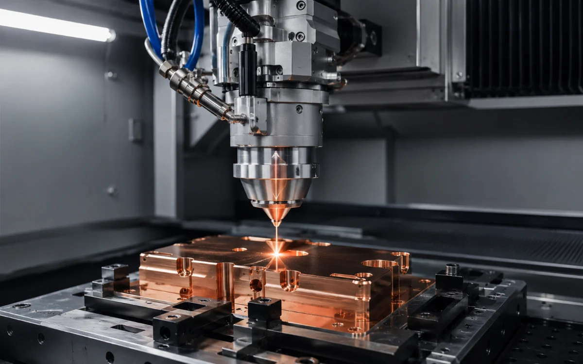
Core takeaway: Material reflectivity is not the same as back-reflected power reaching a fiber laser source. The real risk depends on how much reflected energy re-enters the processing optics, couples into the delivery fiber, travels through its core or cladding, and reaches components that must safely strip, redirect, dissipate, monitor, or interrupt that energy.
A more useful way to understand the problem is:
Workpiece reflection → optical collection → reverse fiber coupling → core/cladding propagation → protection → monitoring → continue, derate, alarm, or shut down.
This distinction matters when selecting industrial fiber laser sources for copper, aluminum, brass, or other reflective-metal processes. A source described simply as having “anti-reflection protection” tells an OEM very little unless the supplier also explains how reverse optical power is handled and what happens when the protection limit is exceeded.
What Is Back Reflection in a Fiber Laser?
Back reflection is laser energy that leaves the processing optics, reflects or scatters from the workpiece, and then couples back into the optical delivery system. Only part of the light reflected at the material surface follows this reverse path toward the source.
A high-power processing beam can be divided conceptually into three parts at the workpiece:
- Energy absorbed by the material
- Energy reflected in one or more directions
- Energy scattered by the interaction zone, plume, melt pool, or surface
Of the reflected and scattered energy, only a fraction is collected by the processing optics. A smaller fraction may then couple back into the delivery fiber.
The nLIGHT patent on back-reflection protection and monitoring describes exactly this mechanism: a material-processing beam can reflect or scatter from a target and become back-coupled into the beam-delivery fiber, with returned light entering both the fiber core and cladding.
That is the optical condition a source-protection system must manage.
Is Material Reflectivity the Same as Back-Reflected Power?
No. Material reflectivity describes how much incident optical energy is reflected at the workpiece, while back-reflected power at the laser depends on how efficiently that reflected light returns through several additional optical stages.
| Quantity | What it means | Why it matters |
|---|---|---|
| Material reflectivity | Fraction of incident optical energy reflected at the workpiece | Indicates the initial absorption challenge |
| Reflected optical power | Power leaving the interaction zone rather than being absorbed | Changes with material state and process conditions |
| Power collected by the head | Reflected light that re-enters the processing optics | Depends strongly on reflection direction and geometry |
| Back-coupled fiber power | Returned energy coupled into the delivery-fiber core or cladding | Directly relevant to source protection |
| Reverse power reaching source stages | Energy remaining after stripping, isolation, or other protection | Determines the actual source-side exposure |
This means it is misleading to take a material reflectivity percentage and assume the same percentage of laser output travels all the way back into the source.
The actual reverse-coupled power depends on:
- Surface finish
- Oxidation and coatings
- Incidence angle
- Workpiece orientation
- Focus position
- Processing-head geometry
- Melt-pool condition
- Keyhole stability
- Scanner or focusing optics
- Fiber acceptance geometry
The value that matters to source survival is therefore not workpiece reflectivity alone. It is the reverse optical energy successfully coupled back into the laser system.
How Does Reflected Laser Light Get Back Into the Fiber?
Returned light that enters the processing head can travel backward through the focusing and collimating optics and reach the process-fiber interface. If its angle and spatial distribution fall within a supported propagation path, part of that energy can couple into the delivery fiber.
Can Back-Reflected Light Enter the Fiber Core?
Yes. Returned light that aligns sufficiently well with the reverse optical path can couple into guided core modes and propagate back toward the source.
This is particularly important because core-propagating light follows an optical path designed to transport very high forward laser power efficiently. Reverse light in this path must therefore be detected, isolated, redirected, or otherwise managed before it reaches vulnerable components.
Can Back-Reflected Light Enter the Fiber Cladding?
Yes. Returned light does not need to couple perfectly into the core to create a problem; some can propagate as cladding light around the guided core region.
The nLIGHT protection architecture specifically addresses backward-propagating cladding light as well as backward core light. The patent notes that uncontrolled cladding light can create excessive heating, damage downstream components or optics, or interfere with laser operation.
This is why a complete protection architecture may need to treat core and cladding return paths differently.
Is Specular Reflection More Dangerous Than Diffuse Reflection?
Specular reflection can be particularly concerning when a smooth surface directs a concentrated reflected beam back toward the processing optics. Diffuse reflection distributes energy across a wider range of angles and may couple less efficiently into the reverse beam path.
However, “specular” does not automatically mean damaging and “diffuse” does not automatically mean safe.
The important questions are:
- How much reflected power enters the head?
- At what angle does it return?
- How efficiently does it couple into the fiber?
- Does it enter the core or cladding?
- What reverse-power level can the protection system tolerate?
Process geometry therefore matters as much as the material label.
Which Materials Create the Highest Back-Reflection Risk?
Highly reflective metals deserve additional attention when processed with common near-infrared industrial fiber lasers. Copper is one of the clearest examples, while aluminum, brass, and other reflective alloys can also create challenging conditions depending on surface and process geometry.
Why Is Copper a Back-Reflection Concern for Fiber Lasers?
Copper initially couples poorly with common near-infrared fiber-laser wavelengths compared with many ferrous materials, while its high thermal conductivity removes heat rapidly from the interaction zone. The source therefore needs sufficient power density to establish stable absorption without creating an uncontrolled transition in the melt or keyhole.
A 2021 Journal of Laser Applications study on hybrid blue-diode and 1060 nm fiber-laser welding of copper specifically examined copper’s high-reflectivity problem and showed that adding shorter-wavelength blue energy increased absorption under the tested conditions.
The practical implication is not that every copper process needs a blue laser. It is that better coupling leaves less incident energy available for reflection.
Are Aluminum and Brass Also Back-Reflection Risks?
They can be. Both can produce significant reflected energy under near-infrared processing conditions, but the actual reverse-coupling risk depends on alloy, surface finish, oxidation, geometry, and process state.
A source supplier should therefore qualify reflective-material capability by application rather than make a vague statement such as “suitable for all metals.”
Does Surface Oxidation or Coating Reduce the Risk?
Surface condition can change initial optical absorption and alter the reflected-power pattern, but oxidation or plating should not be treated as a substitute for source-level protection. Once melting starts, the optical properties of the interaction zone also change.
The Coherent copper-welding work with an Adjustable Ring Mode fiber laser emphasizes that conventional infrared copper welding can be sensitive to surface condition and that controlling spatial power distribution can stabilize the interaction.
When Is Back Reflection Most Dangerous During Processing?
Back reflection is dynamic. The amount and direction of returned energy can change significantly between process startup, piercing, stable cutting, keyhole welding, and an unstable or interrupted process.
Why Can Weld Startup Be More Difficult Than Steady-State Welding?
Before a stable melt pool or keyhole forms, a reflective solid surface may couple less efficiently with the infrared beam. Once stable melting and keyhole behavior are established, the beam interacts with a very different geometry and thermal state.
Coherent’s ARM copper welding research illustrates why controlling the transition into stable welding matters: a high-brightness center beam establishes penetration while surrounding ring power modifies melt-pool behavior and process stability.
The broader conclusion is that reflected power should not be assumed to remain constant throughout the weld.
Why Can Piercing Create Strong Back Reflection?
Before a stable piercing channel forms, the beam repeatedly encounters a comparatively flat surface. Melt ejection, focus position, surface angle, and failed piercing attempts can repeatedly alter the direction of returned energy.
A source that alarms primarily during piercing should therefore be evaluated differently from one that alarms during stable full-speed cutting.
Can Back Reflection Increase Again After a Stable Weld Has Started?
Yes. Keyhole collapse, joint-position changes, contamination, focus errors, sudden gaps, or other process disturbances can change optical coupling and increase reflected energy again.
This is one reason back-reflection monitoring remains useful throughout processing rather than only during initial laser emission.
How Does Back Reflection Damage a Fiber Laser Source?
Back reflection becomes damaging when reverse optical energy reaches locations that cannot safely handle it. Possible effects include localized heating, optical instability, thermal stress, component degradation, protective alarms, and eventually permanent damage.
Can Back Reflection Damage the Delivery Fiber?
Yes. Reverse optical energy in either the core or cladding can create undesirable thermal loading, particularly at interfaces where light is scattered, stripped, absorbed, or concentrated by contamination or defects.
The risk is not simply that “light travels backward.” The problem is where that optical energy eventually ends up.
Can It Damage the QBH or QD Connector?
Connector assemblies can become vulnerable if reflected or scattered optical power creates local heating, especially when contamination introduces an additional absorption point. This is why cleanliness and proper connector handling remain important even when the source itself includes anti-reflection protection.
A source protection system cannot make a contaminated high-power optical interface harmless.
Can Back Reflection Damage Internal Laser Components?
Yes, if sufficient reverse energy propagates beyond the source’s protective stages. The exact vulnerable components depend on the manufacturer’s architecture, so it is not correct to assume that every fiber laser contains the same isolators, combiners, monitoring points, or internal optical layout.
The nLIGHT patent states that back-coupled light can destabilize, damage, or otherwise interfere with a high-power laser system and describes protection specifically intended to remove and monitor backward cladding and core light.
Can Back Reflection Cause Instability Before Permanent Damage?
Yes. A source may detect abnormal reverse power and respond before catastrophic failure occurs. Protective derating, alarms, or shutdowns are evidence that the protection architecture is responding to a potentially harmful operating condition.
An alarm should therefore not automatically be interpreted as proof that the laser has already been damaged.
What Is a Fiber Laser Back-Reflection Alarm?
A back-reflection alarm generally indicates that the source detected an abnormal reverse optical condition or exceeded a related protection threshold. The correct response is to identify why the event occurred before repeatedly restarting the same process.
Why Does the Alarm Happen Only on Copper or Brass?
If steel processes normally but a reflective material repeatedly triggers optical alarms, the material interaction becomes an important diagnostic clue. Source qualification, surface condition, geometry, focus, and process startup should all be reviewed.
The question should not immediately become “Is the source damaged?” but rather:
What changes when this material is placed under the same optical system?
Why Does the Alarm Occur Only During Piercing or Weld Start?
Process initiation often has different optical coupling from steady-state processing. An initially reflective surface, unstable melt, or unfavorable reflection geometry can create a temporary reverse-power event even when the later process is stable.
Should You Immediately Reset a Back-Reflection Alarm?
No. First preserve the alarm information and operating conditions.
Record:
- Material and surface state
- Material thickness
- Whether the event occurred during piercing, cutting, or welding
- Commanded power
- Focus position
- Head/workpiece orientation
- Whether the fault repeats at the same stage
- Connector and processing-head condition
- Relevant source diagnostic information
Repeatedly returning to the same high-reflection condition without understanding its cause can repeatedly load the protection system.
How Does Fiber Laser Back-Reflection Protection Work?
Effective back-reflection protection is best understood as an energy-management chain rather than a single sensor. Different source designs may combine several layers to reduce, remove, absorb, detect, or respond to reverse optical power.
| Protection layer | What it does | What it does not guarantee |
|---|---|---|
| Process-side control | Reduces how much reflected energy couples into the reverse optical path | Cannot eliminate every reflection event |
| Optical isolation or routing | Suppresses or redirects backward propagation | Has finite optical and thermal limits |
| Cladding-light stripping | Removes power propagating in the fiber cladding | Does not automatically remove all core-guided reverse light |
| Controlled heat dissipation | Converts intercepted optical energy into heat at a designed location | Requires sufficient thermal capacity |
| Reverse-power monitoring | Detects abnormal backward optical energy | A detector alone does not absorb the energy |
| Software response | Reduces output or shuts down the laser | May interrupt production and requires the event to be detected |
| Hardware protection | Physically manages returned energy before vulnerable stages | Still has defined engineering limits |
This is why the phrase “anti-reflection protection” is incomplete unless the manufacturer explains what the protection actually does.
What Is a Cladding Light Stripper?
A cladding light stripper is an optical-fiber component designed to remove unwanted light traveling in the fiber cladding. Once removed from the fiber, that optical energy must be dissipated safely rather than allowed to continue toward sensitive components.
Why Does Cladding Light Need to Be Removed?
Cladding-guided power can create unwanted heating at coatings, connectors, splices, and other optical interfaces. Allowing high reverse cladding power to travel deeper into the source can expose components that were never intended to absorb it.
The nLIGHT protection patent describes separate cladding-light stripping locations, including a stripper positioned to remove backward-propagating cladding light returned from the workpiece.
Where Does the Stripped Optical Energy Go?
The removed optical power must ultimately become heat. The protection architecture therefore needs a controlled thermal path capable of absorbing and dissipating that energy.
This is an important point: back-reflection protection is partly an optical problem and partly a thermal-management problem.
What Is Hardware Back-Reflection Protection?
Hardware protection manages returned optical energy physically rather than relying exclusively on shutting the source down after a reflection has been detected. Depending on the architecture, reverse power can be stripped, redirected, absorbed, or dissipated before reaching vulnerable stages.
nLIGHT describes this distinction directly on its back-reflection protection page: its hardware-isolation approach converts returned optical power into heat and dissipates it before it can damage the laser.
What Is Software Back-Reflection Protection?
Software-based protection uses a monitoring signal to detect excessive reverse optical energy and commands the laser to reduce output or shut down when the allowed condition is exceeded. The protective action is primarily a control response.
nLIGHT contrasts this approach with hardware isolation, noting that software-isolated systems may shut off when back reflection is detected and require a reset before production resumes.
Neither concept should be reduced to “good” or “bad.” Their usefulness depends on the source design, permitted reverse load, application, and required production continuity.
What Is an Optical Isolator and How Does It Stop Back Reflection?
An optical isolator is a non-reciprocal optical device designed to favor transmission in one direction while suppressing backward propagation. It is one possible protection element, but it is not automatically equivalent to the complete back-reflection system inside a high-power industrial fiber laser.
IEC 61202-1:2016 defines fiber-optic isolators as passive, non-reciprocal devices with two optical ports for directional transmission of optical power.
Does an Optical Isolator Block 100% of Reflected Light?
No. Optical isolation is finite, and any real component has limits for wavelength, insertion loss, beam properties, forward power, reverse load, and thermal handling.
An isolator specification must therefore be interpreted together with the actual industrial laser architecture rather than as a guarantee that unlimited reflected power can never reach the source.
Can You Add a Laboratory Faraday Isolator to Protect a Multi-kW Fiber Laser?
Not safely without an engineered design. A component suitable for a laboratory beam does not automatically have the aperture, coating, thermal capacity, power rating, beam quality, and reverse-energy handling required by a multi-kilowatt processing system.
Protection for high-power reflective-metal processing should be designed and qualified as part of the complete source and beam-delivery architecture.
What Is Back-Reflection Monitoring?
Back-reflection monitoring uses detectors at selected points in the optical architecture to measure characteristics associated with backward-propagating light. Those signals can trigger diagnostics, alarms, power reduction, or shutdown.
Can the Laser Monitor Core and Cladding Reflection Separately?
Some architectures can. The nLIGHT patent describes detection of characteristics associated with both backward-propagating cladding light and backward-propagating core light, with laser-system behavior adjusted in response to the detected conditions.
Separate monitoring can provide more information than a single generic “reflection detected” signal.
Does a Back-Reflection Sensor Protect the Laser by Itself?
No. A detector measures a condition; it does not necessarily remove the optical energy that created it. Effective protection also needs an optical, thermal, or control response.
This is why protection is better described as:
Detection + energy management + system response.
Can Process Settings Reduce Fiber Laser Back Reflection?
Yes. Process settings can change both how much energy is reflected and where that energy travels, but process optimization should be treated as one protection layer rather than a substitute for source-level protection.
Does Tilting the Laser Head Reduce Back Reflection?
Changing incidence geometry can redirect a specular reflection away from the reverse optical axis in some processes. However, there is no universal “safe” angle for copper, brass, or aluminum processing.
Changing head angle can also alter:
- Focus geometry
- Weld penetration
- Kerf geometry
- Scanner calibration
- Nozzle/gas alignment
- Robot or CNC path planning
Any angle change should therefore be validated as a process parameter, not used as an arbitrary anti-reflection trick.
Does Defocusing Reduce the Risk?
Defocusing increases or decreases spot size depending on direction and optical setup, changing both power density and reflected-light geometry. It may alter reverse coupling, but it also changes the primary cutting or welding process.
A defocused process that prevents an alarm but produces insufficient penetration or poor cut quality is not a valid engineering solution.
Can Beam Wobble or Beam Shaping Help?
They can influence coupling by changing spatial power distribution and melt-pool behavior. Their primary purpose, however, is process control rather than direct source protection.
The Coherent ARM copper work demonstrates how independently controlled center and ring power can stabilize copper welding and reduce sensitivity to difficult material interaction. A more stable process can change the reflection environment, but it does not remove the need for source-level anti-reflection capability.
Why Can Better Copper Absorption Reduce Back-Reflection Risk?
Optical energy absorbed by the workpiece is no longer available to be reflected. Improving energy coupling can therefore reduce the optical power available for reverse coupling into the processing head.
Why Do Blue and Green Lasers Couple Better Into Copper?
Copper generally absorbs shorter visible wavelengths more strongly than common near-infrared fiber-laser wavelengths under many initial surface conditions. This can make the transition into melting more predictable.
The 2021 hybrid blue and fiber-laser copper study reported improved absorption when a 450 nm blue diode source was combined with a 1060 nm fiber laser under its experimental conditions.
That result should not be interpreted as a universal recipe, but it clearly demonstrates the relationship between wavelength, absorption, and available reflected energy.
Does Better Absorption Eliminate Back Reflection?
No. Better coupling reduces the amount of incident energy available for reflection but does not guarantee zero reverse power. Workpiece geometry, surface changes, process instability, and optical collection still matter.
Why Are Infrared Fiber Lasers Still Used for Copper?
Infrared fiber lasers remain attractive because they combine high power, mature fiber delivery, strong electrical efficiency, compact integration, and flexible beam-control technologies. High-brightness beams, power ramps, beam shaping, core-ring architectures, and source-level reflection protection have expanded their ability to process copper.
The key engineering question is therefore not simply “Is infrared reflected by copper?” but:
Can the complete source and process establish stable coupling while safely managing the reverse energy that remains?
How Can You Tell Whether Back Reflection Has Already Damaged the Source?
A back-reflection alarm alone does not prove permanent source damage. Persistent changes after the process condition is corrected provide much stronger evidence that service inspection is needed.
Warning signs can include:
- Repeated optical or reflection alarms under previously stable conditions
- New output-power instability
- Measured source power below specification
- Unusual connector heating
- Persistent scattered-light or internal optical alarms
- Visible process-fiber or connector damage
- Internal module faults
- Failure to return to normal READY/emission states after an approved reset
None of these symptoms is unique to back reflection. Contaminated optics, cooling faults, electrical problems, connector damage, and other source failures must still be excluded.
What Should You Check After a Back-Reflection Alarm?
Preserve the event data first, then determine whether the fault correlates with material, process stage, geometry, power, or an optical-condition change. Do not repeatedly reproduce the same high-reflection event simply to see whether the source shuts down again.
- Record the exact alarm and timestamp.
- Record material and alloy.
- Check surface finish, coating, oxidation, and contamination.
- Identify whether the alarm occurred during piercing, weld start, stable processing, or process interruption.
- Record commanded laser power.
- Record focus position.
- Check head and workpiece orientation.
- Inspect accessible protective optics according to the manufacturer’s procedure.
- Review connector and fiber condition without opening protected high-power interfaces.
- Save the source diagnostic log.
- Determine whether the fault occurs only on one material or geometry.
- Verify source output after the event using an approved test method where necessary.
- Escalate repeated optical faults to the source or machine manufacturer.
What Should an OEM Ask About Back-Reflection Protection Before Buying a Fiber Laser?
The phrase “anti-reflection protection” is too vague for an OEM specification. Buyers integrating a source into copper, brass, aluminum, or other reflective-metal equipment should ask how reverse power is managed and what operating limitations remain.
Ask the supplier:
- Is the source explicitly approved for the target reflective material?
- Which copper, aluminum, or brass applications have been validated?
- Is protection hardware-based, software-based, or both?
- Is backward core power monitored?
- Is backward cladding power monitored?
- Does the architecture strip backward cladding light?
- How is intercepted reverse optical energy dissipated?
- What happens when the reflection threshold is exceeded?
- Does the source continue, derate, or shut down?
- Are reflection events recorded in diagnostics?
- Are there restrictions on perpendicular or highly specular processing geometries?
- Which output connector and processing-head combinations are approved?
- Does reflective-material processing change warranty requirements?
When comparing fiber laser source options for reflective-metal processing, this information is more useful than a simple checkbox saying “anti-reflection: yes.”
What Is the Quickest Way to Reduce Fiber Laser Back-Reflection Risk?
The most reliable strategy combines a source qualified for the application with clean optics, suitable beam geometry, stable process coupling, and active protection. No single process trick should be expected to replace proper source architecture.
- Confirm material qualification. Make sure the source is approved for the reflective material and target power range.
- Verify the beam-delivery system. Connector, process fiber, head, and optics must all be suitable for the source power.
- Keep optical interfaces clean. Contamination creates additional absorption and thermal risk.
- Validate workpiece geometry. Avoid untested orientations that direct strong specular reflection into the optical axis.
- Develop a stable process window. Focus, power, speed, ramps, beam shape, and piercing strategy should produce stable coupling.
- Keep protection enabled. Do not bypass back-reflection alarms or optical interlocks.
- Preserve diagnostic data. Repeated reflection events should be investigated rather than repeatedly reset.
- Escalate persistent faults. Internal optical alarms require manufacturer-level diagnosis when machine-side causes have been excluded.
Frequently Asked Questions About Fiber Laser Back Reflection
Can Back Reflection Destroy a Fiber Laser Source?
Yes. Sufficient reverse optical power can create thermal loading, instability, or component damage when it exceeds the source’s protection capability. Material reflectivity alone, however, does not tell you how much optical power actually reaches the source.
Is Copper Safe to Process With a Fiber Laser?
Yes, when the source and beam-delivery system are qualified for reflective-metal processing and the process is properly validated. Copper remains challenging because its initial near-infrared coupling is relatively poor and its thermal conductivity is high.
Does Tilting the Cutting or Welding Head Prevent Back Reflection?
Changing incidence angle can redirect specular reflection in some processes, but there is no universal safe tilt angle. Head geometry, focus, joint design, process quality, and source protection must be validated together.
Does a Back-Reflection Alarm Mean the Laser Is Already Damaged?
No. It normally means that a protection system detected an abnormal reverse optical condition and responded. Permanent damage should only be assessed after the process cause is corrected and source output, diagnostics, fiber, connector, and optical condition are verified.